Air Cylinder, Standard Type, Double Acting, Single Rod CA2 Series
Caution
- See catalog for specification details.
- Product pictures are representations. CAD data is not supported for some model numbers.
Product Description
An air cylinder with easy air cushion control.
[Features]
· Weight reduced by up to 15%.
· Various switches such as compact auto switches and strong magnetic field resistant switches can be mounted.
· Part numbers are set for products with rod-end brackets and pivot brackets. (No need to order separately.)
*See catalog for specification details.
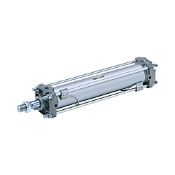
Air Cylinder, Standard Type, Double Acting, Single Rod CA2 Series Specifications

Air Cylinder, Standard Type, Double Acting, Single Rod CA2 Series external appearance

Symbol Double acting Air cushion
Specifications
| Tube Internal Diameter (mm) | 40 | 50 | 63 | 80 | 100 | ||
|---|---|---|---|---|---|---|---|
| Applicable fluids | Air | ||||||
| Operating method | Double acting | ||||||
| Proof pressure | 1.5 MPa | ||||||
| Maximum operating pressure | 1.0 MPa | ||||||
| Ambient temperature and working fluid temperature | Without auto switch: -10°C to 70°C*1 With auto switch: -10°C to 60°C*1 | ||||||
| Minimum operating pressure | 0.05 MPa | ||||||
| Operating piston speed | 50 to 500 mm/s | ||||||
| Cushioning | Air cushion or rubber bumper | ||||||
| Stroke length tolerance | Up to 250st: (0 to +1.0) 251 to 1,000st: (0 to +1.4) 1,001 to 1,500st: (0 to +1.8) 1,501 to 1,800st: (0 to +2.2) | ||||||
| Lubrication | Not required (non-lube) | ||||||
| Mounting style | Basic type, foot type, rod-end flange type, head-end flange type single clevis type, double clevis type, center trunnion type | ||||||
| Allowable kinetic energy (J)*2 | Air cushion | When activated | 2.8 | 4.6 | 7.8 | 16 | 29 |
| When not activated | 0.33 | 0.56 | 0.91 | 1.5 | 2.68 | ||
| Rubber cushion | 1.8 | 3.6 | 6.0 | 12.0 | 12.0 | ||
- *1No freezing.
- *2Activate the air cushion when operating the cylinder. If this is not done, the piston rod assembly or the tie-rods will be damaged if the allowable kinetic energy exceeds the values shown in the above table.
Standard Strokes
| Bore size | Standard strokeNote 1) | Max. manufacturable stroke | |
|---|---|---|---|
| Stroke range (1) | Stroke range (2) | ||
| 40 | 25, 50, 75, 100, 125, 150, 175, 200, 250, 300, 350, 400, 450, 500 | Up to 1,800 | Up to 2,700 |
| 50, 63 | 25, 50, 75, 100, 125, 150, 175, 200, 250, 300, 350, 400, 450, 500, 600 | ||
| 80, 100 | 25, 50, 75, 100, 125, 150, 175, 200, 250, 300, 350, 400, 450, 500, 600, 700 | ||
Note 1) Intermediate strokes not listed above are produced to order.
Note 2) Applicable strokes should be confirmed according to the usage. For details, please refer to "Air Cylinder Model Selection" in the manufacturer's catalog. In addition, products that exceed stroke range 1 may not be able to fulfill the specifications due to deflection, etc.
Note 3) Please consult with the manufacturer for manufacturability and the part numbers when exceeding the stroke range 2.
Note 4) The stroke range with rod boot is 20 to 1,800 mm. Please consult with the manufacturer support center when exceeding 1,800 mm strokes.
Mounting Brackets / Part No.
(Unit: mm)
| Tube Internal Diameter (mm) | 40 | 50 | 63 | 80 | 100 |
|---|---|---|---|---|---|
| Axial foot*1 | CA2-L04 | CA2-L05 | CA2-L06 | CA2-L08 | CA2-L10 |
| Flange | CA2-F04 | CA2-F05 | CA2-F06 | CA2-F08 | CA2-F10 |
| Single clevis | CA2-C04 | CA2-C05 | CA2-C06 | CA2-C08 | CA2-C10 |
| Double clevis*2 | CA2-D04 | CA2-D05 | CA2-D06 | CA2-D08 | CA2-D10 |
- *1When axial foot brackets are used, order two pieces per cylinder.
- *2A clevis pin, flat washers and split pins are shipped together with the clevis types.
Allowable Kinetic Energy

Allowable Kinetic Energy graph
Example) Find the upper limit of rod-end load when an air cylinder of ø63 is operated at 500 mm/s.
From a point indicating 500 mm/s on the horizontal axis, extend a line upward and find a point where it intersects with a line for the 63‑mm bore size. Extend a line from the intersection to the left and find a load mass of 60 kg.
Dimensional Outline Drawing (Dimensions Other Than Those Shown Below Are the Same As the Standard Type)

CA2 Series dimensional outline drawing
(Unit: mm)
| Tube I.D. | øe | f |
|---|---|---|
| 40 | 26 | 13.5 |
| 50 | 30 | 12.5 |
| 63 | 30 | 12.5 |
| 80 | 36 | 16.5 |
| 100 | 42 | 16 |
- *The mounting dimensions of the mounting bracket are the same as the standard type.
- *See the manufacturer's catalog for details.
Structural drawing

CA2 Series Structural Drawing
Component Parts
| Number | Description | Material | Note |
|---|---|---|---|
| 1 | Rod Cover | Die-cast aluminum | Trivalent chromated |
| 2 | Head cover | Die-cast aluminum | Trivalent chromated |
| 3 | Cylinder tube | Aluminum Alloy | Hard Anodize |
| 4 | Piston rod | Carbon steel | Hard chrome plating |
| 5 | Piston | Aluminum Alloy | - |
| 6 | Cushion ring | Aluminum Alloy | Anodized |
| 7 | Cushion ring B | Aluminum Alloy | Anodized |
| 8 | Bushing | Resin/Copper alloy (Multiple layers) | - |
| 9 | Cushion valve | Steel wire | Trivalent zinc chromated |
| 10 | Tie-rod | Carbon steel | Trivalent zinc chromated |
| 11 | Retaining Ring | Steel for spring | Phosphate coated |
| 12 | Spring washer | Steel wire | Trivalent zinc chromated |
| 13 | Tie-rod nut | Rolled steel | Trivalent zinc chromated |
| 14 | Wear ring | Resin | - |
| 15 | Cushion seal | Urethane | - |
| 16 | Rod Gasket | NBR | - |
| 17 | Piston Gasket | NBR | - |
| 18 | Cushion valve seal | NBR | - |
| 19 | Cylinder tube gasket | NBR | - |
| 20 | Rod-end nut | Rolled steel | Trivalent zinc chromated |
Replacement Parts / Seal Kit
| Bore size (mm) | Order number | Content |
|---|---|---|
| 40 | CA2-40Z-PS | Set of nos. (15), (16), (17), (19) |
| 50 | CA2-50Z-PS | |
| 63 | CA2-63Z-PS | |
| 80 | CA2-80Z-PS | |
| 100 | CA2-100Z-PS |
- *Seal kit includes 15, 16, 17 and 19. Order the seal kit based on each bore size.
- *Do not disassemble the trunnion type. Refer to the manufacturer's catalog.
- *Seal kit includes a grease pack (ø40, ø50: 10 g, ø63, ø80: 20 g, ø100: 30 g). Order with the following part number when only the grease pack is needed. Grease pack part number: GR-S-010 (10 g), GR-S-020 (20 g)
- *Product pictures are representations. CAD data is not supported for some model numbers.
- *See the manufacturer's catalog for other specifications, standard type, included fitting dimensions, etc.