Air Cylinder, Standard Type, Double Acting, Double Rod MBW Series

Caution
- ■ SMC Product Line
Webpages for products currently without individual pages on this site will be released on an ad-hoc basis. - Refer to the manufacturer's catalog for specification and material details.
- Product images may be representative images. Refer to the manufacturer's catalog for shape details.
- CAD data is not supported for some model numbers.
Product Description
A standard type double action, double rod cylinder.
[Features]
· A lightweight air cylinder with a weight reduction of up to 10% thanks to the changed cover shape.
· Part numbers are set for products with rod-end brackets and pivot brackets (no need to order separately).
*See the SMC catalog for specification details.
*Product pictures are representative images. CAD data is not supported for some model numbers.
Air Cylinder, Standard Type, Double Acting, Double Rod MBW Series Specifications
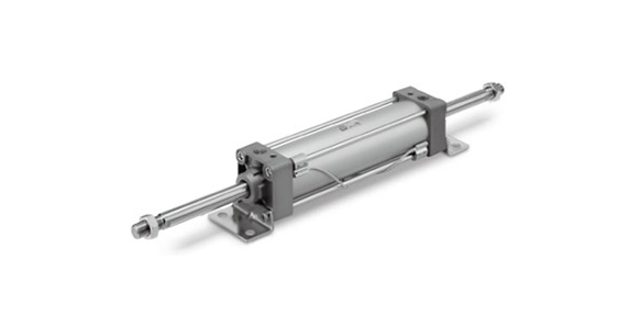
Air Cylinder, Standard Type, Double Acting, Double Rod MBW Series external appearance
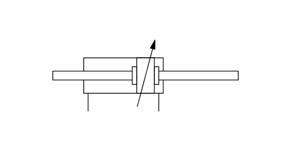
JIS symbol (Double acting type, air cushion)
Specifications
| Tube Inner Diameter (mm) | 32 | 40 | 50 | 63 | 80 | 100 | 125 |
|---|---|---|---|---|---|---|---|
| Action | Double acting, double rod | ||||||
| Fluid | Air | ||||||
| Proof Pressure | 1.5 MPa | ||||||
| Maximum operating pressure | 1.0 MPa | ||||||
| Minimum operating pressure | 0.05 MPa | ||||||
| Ambient and Fluid Temperature | Without auto switch: -10°C to 70°C (no freezing) With auto switch: -10°C to 60°C (no freezing) | ||||||
| Lubrication | Not required (non-lubricated) | ||||||
| Piston Speed | 50 to 1,000 mm/s | 50 to 700 mm/s | |||||
| Stroke Length Tolerance | Up to 250: (0 to +1.0), 251 to 1,000: (0 to +1.4), 1,001 to 1,500 | ||||||
| Cushion* | Air cushion or rubber bumper | ||||||
| Connection Port Size (Rc, NPT, G) | 1/8 | 1/4 | 3/8 | 1/2 | |||
| Mount Support Type | Basic type, foot type, flange type, center trunnion type | ||||||
*Kinetic energy absorbable by the cushion mechanism is the same as double acting, single rod type.
Stroke Table
(Units: mm)
| Tube Internal Diameter | Standard Stroke | Manufacturable Maximum Stroke | |
|---|---|---|---|
| Stroke Range (1) | Stroke range (2) | ||
| 32 | 25, 50, 75, 100, 125, 150, 175, 200, 250, 300, 350, 400, 450, 500 | Up to 1,000 | 1,800 |
| 40 | 25, 50, 75, 100, 125, 150, 175, 200, 250, 300, 350, 400, 450, 500 | ||
| 50 | 25, 50, 75, 100, 125, 150, 175, 200, 250, 300, 350, 400, 450, 500, 600 | Up to 1,200 | |
| 63 | 25, 50, 75, 100, 125, 150, 175, 200, 250, 300, 350, 400, 450, 500, 600 | ||
| 80 | 25, 50, 75, 100, 125, 150, 175, 200, 250, 300, 350, 400, 450, 500, 600, 700, 800 | Up to 1,500 | |
| 100 | 25, 50, 75, 100, 125, 150, 175, 200, 250, 300, 350, 400, 450, 500, 600, 700, 800 | ||
| 125 | 25, 50, 75, 100, 125, 150, 175, 200, 250, 300, 350, 400, 450, 500, 600, 700, 800, 900, 1,000 | ||
- *1: Consult with SMC regarding intermediate strokes. (Spacers are not used.)
- *2: The applicable stroke should be confirmed according to the usage. See the SMC catalog for details. In addition, products that exceed stroke range 1 may not be able to meet the specifications due to deflection, etc.
- *3: Contact SMC for information regarding manufacturability and part numbers when exceeding stroke range 2.
- *4: The stroke range when with the rod boot is up to 1,000 mm. Contact SMC when exceeding 1,000 mm.
Theoretical Output Table

Out (left) / In (right)
(Unit: N)
| Tube Internal Diameter (mm) | Rod Diameter (mm) | Operating Direction | Piston Area (mm2) | Operating Pressure (MPa) | ||||||||
|---|---|---|---|---|---|---|---|---|---|---|---|---|
| 0.2 | 0.3 | 0.4 | 0.5 | 0.6 | 0.7 | 0.8 | 0.9 | 1.0 | ||||
| 32 | 12 | IN/OUT | 691 | 138 | 207 | 276 | 346 | 415 | 484 | 553 | 622 | 691 |
| 40 | 16 | IN/OUT | 1,056 | 211 | 317 | 422 | 528 | 634 | 739 | 845 | 950 | 1,056 |
| 50 | 20 | IN/OUT | 1,649 | 330 | 495 | 660 | 825 | 989 | 1,154 | 1,319 | 1,484 | 1,649 |
| 63 | 20 | IN/OUT | 2,803 | 561 | 841 | 1,121 | 1,402 | 1,682 | 1,962 | 2,242 | 2,523 | 2,803 |
| 80 | 25 | IN/OUT | 4,536 | 907 | 1,361 | 1,814 | 2,268 | 2,722 | 3,175 | 3,629 | 4,082 | 4,536 |
| 100 | 30 | IN/OUT | 7,147 | 1,429 | 2,144 | 2,859 | 3,574 | 4,288 | 5,003 | 5,718 | 6,432 | 7,147 |
| 125 | 32 | IN/OUT | 11,468 | 2,294 | 3,440 | 4,588 | 5,734 | 6,881 | 8,028 | 9,174 | 10,321 | 11,468 |
*Theoretical output (N) = Pressure (MPa) × Piston area (mm2).
Weight Table / Aluminum Tube
(Unit: kg)
| Tube Inner Diameter (mm) | 32 | 40 | 50 | 63 | 80 | 100 | 125 | |
|---|---|---|---|---|---|---|---|---|
| Basic weight | Basic type | 0.56 | 0.78 | 1.37 | 1.64 | 3.05 | 4.23 | 6.48 |
| Foot type | 0.68 | 0.92 | 1.59 | 1.92 | 3.55 | 4.89 | 8.56 | |
| Flange type | 0.85 | 1.15 | 1.82 | 2.43 | 4.50 | 7.54 | 10.64 | |
| Trunnion Type | 0.85 | 1.14 | 1.85 | 2.44 | 4.60 | 7.90 | 9.46 | |
| Additional weight per 50 strokes | All mounting brackets | 0.15 | 0.24 | 0.37 | 0.38 | 0.61 | 0.82 | 1.02 |
| Accessories | Single Knuckle | 0.15 | 0.23 | 0.26 | 0.26 | 0.60 | 0.83 | 1.08 |
| Double Knuckle (with Pin) | 0.22 | 0.37 | 0.43 | 0.43 | 0.87 | 1.27 | 1.58 | |
Calculation (Example) MBWB32-100Z (basic type, ø32 mm, 100 st)
- Basic weight: 0.56 kg (Basic type, ø32 mm)
- Additional weight: 0.15 kg/50 stroke
- Cylinder stroke: 100 stroke
0.56 + 0.15 × 100/50 = 0.86 kg
Diagram
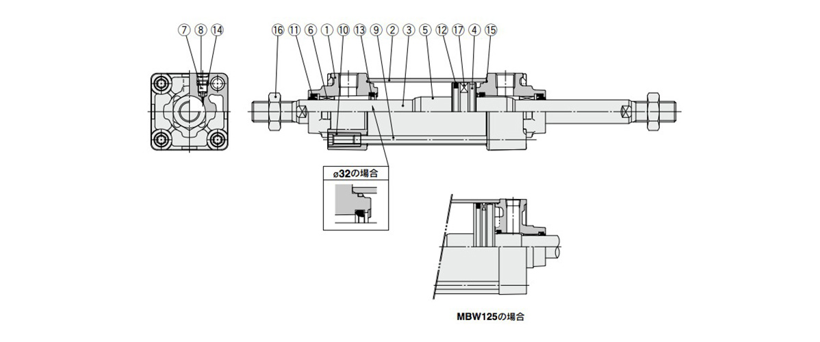
Air Cylinder, Standard Type, Double Acting, Double Rod MBW Series diagram
| Number | Name | Material | Quantity | Notes |
|---|---|---|---|---|
| 1 | Rod cover | Diecast aluminum | 2 | Trivalent chromated |
| 2 | Cylinder Tubing | Aluminum alloy | 1 | Hard anodized aluminum |
| 3 | Piston rod | Carbon steel | 1 | Hard chrome plating |
| 4 | Piston | Aluminum alloy | 1 | - |
| 5 | Cushion Ring | Aluminum alloy | 2 | Anodized aluminum |
| 6 | Bushing | Bearing alloy | 2 | - |
| 7 | Cushion Valve | Steel wire | 2 | Zinc trivalent chromate |
| 8 | Retaining Ring | Steel for spring | 2 | ø40 to 25 mm |
| 9 | Tie-Rod | Carbon steel | 4 | Zinc trivalent chromate |
| 10 | Tie-Rod Nut | Carbon steel | 8 | Zinc trivalent chromate |
| 11 | Rod Seal | NBR | 2 | - |
| 12 | Piston Seal | NBR | 1 | - |
| 13 | Cushion Seal | Urethane | 2 | - |
| 14 | Cushion Valve Seal | NBR | 2 | - |
| 15 | Cylinder Tube Gasket | NBR | 2 | - |
| 16 | Rod End Nut | Rolled steel | 2 | Zinc trivalent chromate |
| 17 | Magnet | - | (1) | - |
- *Seal kit includes 11, 12, 13 and 15. Order the seal kit using the kit number corresponding to each tube inner diameter.
- *Do not disassemble the trunnion type. (See the SMC catalog)
- *The seal kit includes a grease pack. (ø32 to 50 mm: 10 g, ø63 mm and ø80 mm: 20 g, ø100 mm and ø125 mm: 30g).
- *Contact SMC if it is necessary to order a grease pack separately.
Dimensions
(Units: mm)
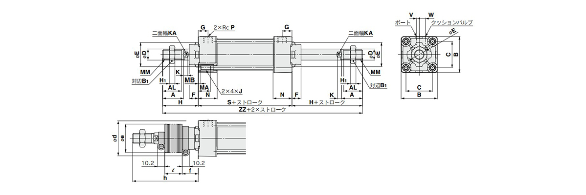
Basic type: (B) dimensional drawing
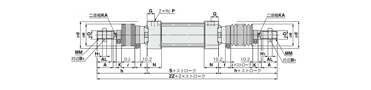
Basic type: (B) with rod boot dimensional drawing
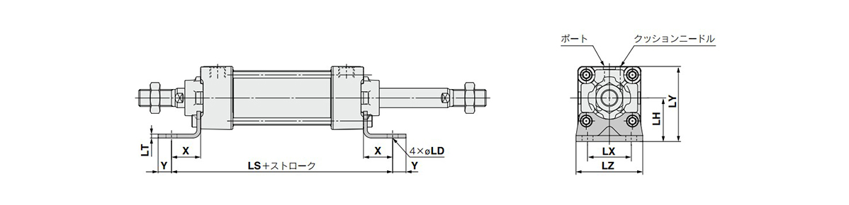
Foot type: (L) dimensional drawing
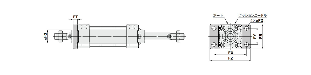
Rod-end flange type: (F) dimensional drawing
- *See the manufacturer's catalog for dimensional drawings and values other than those provided above.
- *Models without air cushion will have a rubber bumper. As bumpers are attached to both sides of the piston, the overall length is increased as follows: ø32 mm and ø40 mm: 6 mm, ø50 mm and ø63 mm: 8 mm, ø80 mm and ø100 mm: 10 mm, ø125 mm: 12 mm.
- *Models without air cushion will have a rubber bumper. As bumpers are attached to both sides of the piston, the Z dimension is increased as follows: ø32 mm and ø40 mm: 3 mm, ø50 mm and ø63 mm: 4 mm, ø80 mm and ø100 mm: 5 mm, ø125 mm: 6 mm. (With trunnion type)