Driving Equipment High Multi-Cylinder

Caution
- The product images are representative only. Please refer to the catalog for shape details.
Product Description
Mounted directly without mounting hardware, slim shape with embedded sensor switch.
Drawing
⌀6·⌀10·⌀16
Cautions: For standard cylinders, dimensions A to D with a stroke of 5 mm are the dimensions of the sensor cylinder.
⌀20
Product Specifications
Mounted directly without mounting hardware, slim shape with embedded sensor switch.
Compact, direct mountWith a square body and 6-sided mounting, it can be mounted compactly and directly.
Standardized cylinder with guideEquipped with a linear guide, pursuing space saving and non-rotating accuracy.
Uses a recessed sensor switchUses a recessed sensor switch that does not protrude from the main body. Used by recessing it in the sensor mounting groove on the 2 sides of the main body.
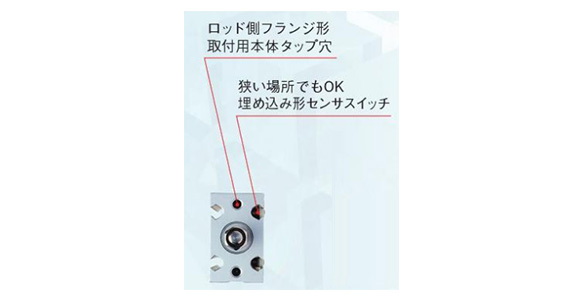
Rod side flange type, main body tapped hole for mounting
OK even in a small place. Recessed sensor switch
Flat mounting with reduced height
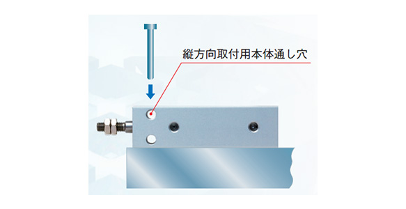
Main body through hole for vertical mounting
Vertical mounting with narrowed width
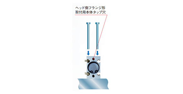
Head side flange type, main body tapped hole for mounting
Space-saving flange type mounting
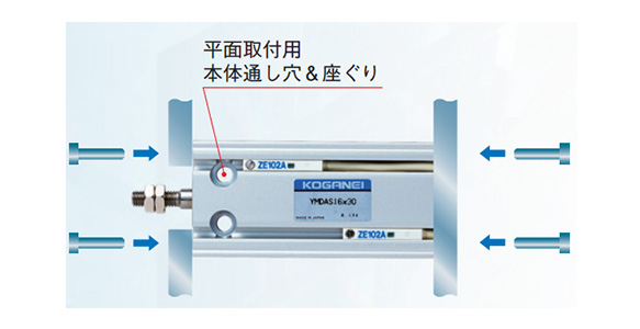
Main body through hole & counterbore for flat mounting
| Items | Cylinder diameter | ||||
|---|---|---|---|---|---|
| 6 | 10 | 16 | 20 | ||
| Operation type | Double acting type, push/pull single acting type | ||||
| Operating fluid | Air | ||||
| Operating Pressure Range MPa | Double acting type | 0.15 to 0.7 | 0.1 to 0.7 | 0.08 to 0.7 | |
| Single acting push type | 0.2 to 0.7 | 0.15 to 0.7 | |||
| Single Acting Instroke Type | 0.3 to 0.7 | 0.2 to 0.7 | 0.15 to 0.7 | ||
| Proof pressure (MPa) | 1.05 | ||||
| Operating temperature range °C | 0 to 60 | ||||
| Operating speed range mm/s | 50 to 500^* | ||||
| Cushion | Rubber bumper method | ||||
| Lubrication | Not required (When refueling, turbine oil type 1 "ISO VG32" equivalent) | ||||
| Piping connection port diameter | M5 × 0.8 | ||||
Cautions: If the stroke exceeds 30 mm with ø6 (cylinder diameter 6 mm), it will be 100 to 500 mm/s.
Cylinder diameter and stroke
| Operation type | Diameter | Standard stroke | Max. manufacturable stroke |
|---|---|---|---|
| Double acting type | 6 | 5, 10, 15, 20, 25, 30, 40, 50, 60 | 60 |
| 10 | |||
| 16 | |||
| 20 | 5, 10, 15, 20, 25, 30, 40, 50, 60, 70, 80, 90, 100 | 100 | |
| Single acting push type Single Acting Instroke Type | 6 | 5, 10, 15 | 15 |
| 10 | |||
| 16 | |||
| 20 |
Force
| Cylinder diameter mm | Piston rod diameter mm | Operation | Pressure receiving area mm^2 | Air pressure MPa | |||||||
|---|---|---|---|---|---|---|---|---|---|---|---|
| 0.1 | 0.2 | 0.3 | 0.4 | 0.5 | 0.6 | 0.7 | |||||
| 6 | 3 | Double acting type | Push side | 28.2 | — | 5.6 | 8.5 | 11.3 | 14.1 | 16.9 | 19.7 |
| Pull side | 21.2 | — | 4.2 | 6.4 | 8.5 | 10.6 | 12.7 | 14.8 | |||
| Single acting push type | 28.2 | — | 0.7 | 3.5 | 6.4 | 9.2 | 12.0 | 14.8 | |||
| Single Acting Instroke Type | 21.2 | — | — | 1.5 | 3.6 | 5.7 | 7.8 | 9.9 | |||
| 10 | 5 | Double acting type | Push side | 78.5 | 7.9 | 15.7 | 23.6 | 31.4 | 39.3 | 47.1 | 55 |
| Pull side | 58.9 | 5.9 | 11.8 | 17.7 | 23.6 | 29.5 | 35.3 | 41.2 | |||
| Single acting push type | 78.5 | — | 6.1 | 13.9 | 21.8 | 29.6 | 37.5 | 45.4 | |||
| Single Acting Instroke Type | 58.9 | — | 2.2 | 8.1 | 13.9 | 19.8 | 25.7 | 31.6 | |||
| 16 | 6 | Double acting type | Push side | 201 | 20.1 | 40.2 | 60.3 | 80.4 | 100.5 | 120.6 | 140.7 |
| Pull side | 172 | 17.2 | 34.4 | 51.6 | 68.8 | 86 | 103.2 | 120.4 | |||
| Single acting push type | 201 | — | 18.8 | 38.9 | 59.0 | 79.1 | 99.2 | 119.3 | |||
| Single Acting Instroke Type | 172 | — | 13.0 | 30.2 | 47.4 | 64.6 | 81.8 | 99.0 | |||
| 20 | 10 | Double acting type | Push side | 314 | 31.4 | 62.8 | 94.2 | 125.6 | 157 | 188.4 | 219.8 |
| Pull side | 235 | 23.5 | 47 | 70.5 | 94 | 117.5 | 141 | 164.5 | |||
| Single acting push type | 314 | — | 44 | 75.4 | 106.8 | 138.2 | 169.6 | 201 | |||
| Single Acting Instroke Type | 235 | — | 28.2 | 51.7 | 75.2 | 98.7 | 122.2 | 145.7 | |||
Standard table
⌀6·⌀10·⌀16
| Type | Standard cylinder^* | Sensor Cylinder | E | F | G | H | I | J | K | L | ||||||
|---|---|---|---|---|---|---|---|---|---|---|---|---|---|---|---|---|
| Diameter | A | B | C | D | A | B | C | D | ||||||||
| 6 | 43 | 28 | 21 | 2 | 48 | 33 | 26 | 7 | 15 | 7 | 11 | 7 | 5.5 | 1.8 | M3 × 0.5 | M3 × 0.5, Depth 5 |
| 10 | 48 | 31 | 23 | 2.5 | 53 | 36 | 28 | 7.5 | 17 | 8 | 11 | 10 | 7 | 2.4 | M4 × 0.7 | M3 × 0.5, Depth 5 |
| 16 | 53 | 35 | 26 | 3 | 58 | 40 | 31 | 8 | 18 | 9 | 14 | 12 | 8 | 3.2 | M5 × 0.8 | M4 × 0.7, Depth 6 |
| Diameter | M | N | O | P | Q | R | S | T | V | Y |
|---|---|---|---|---|---|---|---|---|---|---|
| 6 | 15.5 | 10.5 | 3.4 | 8 | 7 | ø3.4 Counterbore ø6 Depth 5 (both sides) | 24 | 13 | 3 | 19 |
| 10 | 18 | 10.5 | 3.4 | 10 | 8 | ø3.4 Counterbore ø6 Depth 5 (both sides) | 25 | 15 | 5 | 19 |
| 16 | 20 | 12 | 4.5 | 12 | 9 | ø4.5 Counterbore ø7.6 Depth 6.5 (both sides) | 33 | 20 | 6 | 25 |
⌀20
| Type | Standard Cylinder | Sensor Cylinder | ||||||
|---|---|---|---|---|---|---|---|---|
| Diameter | A | B | C | D | A | B | C | D |
| 20 | 61 | 40 | 31 | 8.5 | 71 | 50 | 41 | 18.5 |
Behind the scenes
This product was developed through rigorous testing to meet the customers' needs by combining the design expertise and
production technology that the manufacturer has cultivated since its founding.