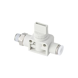
Hand Shut-Off Valve – Straight Type B (2/3-Way)
Caution
- The product images are representative only. See the product standards for details.
Product Description
[Features]
·Capable of opening and closing air pressure inlet to equipment
·3-direction valve type and 2-direction valve type are available
·The 3-direction valve type exhausts the residual pressure on the output side when closed
·Selectable from 4 types according to applications
Drawing

Product Specifications
Product Specifications
| Operating fluid | Air |
|---|---|
| Maximum operating pressure | 0.9 MPa |
| Operating vacuum pressure | -100 kPa |
| Operating temperature range | 0 to +60°C (no freezing) |
Standard table
| Model | Tube Outer Diameter ⌀D | R | A | E1 | E2 | L | ⌀P1 | ⌀P2 | Tube End C | B1 | B2 | Width across flats H | F1 | F2 | Effective Cross-sectional area (mm^2) | Weight (g) |
|---|---|---|---|---|---|---|---|---|---|---|---|---|---|---|---|---|
| HV01-6- (3)(4) | 6 | R1/8 | 8 | 17 | 40.5 | 55.9 | 12.5 | 16.5 | 17 | 33.5 | 26.4 | 14 | 18 | 8 | 8.3 | 34 |
| HV02-6- (3)(4) | R1/4 | 11 | 56.8 | 36.5 | 8.5 | 40 | ||||||||||
| HV03-6- (3)(4) | R3/8 | 12 | 58.3 | 38.3 | 17 | 8.2 | 53 | |||||||||
| HV01-8- (3)(4) | 8 | R1/8 | 8 | 17 | 40.5 | 57.2 | 15 | 16.5 | 18.1 | 33.5 | 27.7 | 14 | 18 | 8 | 8.9 | 35 |
| HV02-8- (3)(4) | R1/4 | 11 | 58.2 | 36.5 | 41 | |||||||||||
| HV03-8- (3)(4) | R3/8 | 12 | 59.7 | 38.3 | 17 | 54 | ||||||||||
| HV02-10- (3)(4) | 10 | R1/4 | 11 | 21.7 | 41 | 68.7 | 17.5 | 19.5 | 20.2 | 42.5 | 32.2 | 17 | 24 | 11 | 16.6 | 62 |
| HV03-10- (3)(4) | R3/8 | 12 | 69.4 | 43.5 | 16.9 | 71 | ||||||||||
| HV04-10- (3)(4) | R1/2 | 15 | 70.5 | 46.5 | 21 | 16.5 | 93 | |||||||||
| HV02-12- (3)(4) | 12 | R1/4 | 11 | 21.7 | 41 | 71.4 | 21 | 19.5 | 23.4 | 42.5 | 34.9 | 17 | 24 | 11 | 17 | 66 |
| HV03-12- (3)(4) | R3/8 | 12 | 72.1 | 43.5 | 17.1 | 74 | ||||||||||
| HV04-12- (3)(4) | R1/2 | 15 | 73.2 | 46.5 | 21 | 16.8 | 96 | |||||||||
| HV01-1/4- (3)(4) | 1/4 | R1/8 | 8 | 17 | 40.5 | 55.9 | 12.5 | 16.5 | 17 | 33.5 | 26.4 | 14 | 18 | 8 | 8.7 | 34 |
| HV02-1/4- (3)(4) | R1/4 | 11 | 56.8 | 36.5 | 8.4 | 40 | ||||||||||
| HV03-1/4- (3)(4) | R3/8 | 12 | 58.3 | 38.3 | 17 | 8.5 | 53 | |||||||||
| HV01-5/16- (3)(4) | 5/16 | R1/8 | 8 | 17 | 40.5 | 57.2 | 15 | 16.5 | 18.1 | 33.5 | 27.7 | 14 | 18 | 8 | 8.9 | 35 |
| HV02-5/16- (3)(4) | R1/4 | 11 | 58.2 | 36.5 | 41 | |||||||||||
| HV03-5/16- (3)(4) | R3/8 | 12 | 59.7 | 38.3 | 17 | 54 | ||||||||||
| HV02-3/8- (3)(4) | 3/8 | R1/4 | 11 | 21.7 | 41 | 68.7 | 17.5 | 19.5 | 20.2 | 42.5 | 32.2 | 17 | 24 | 11 | 16.5 | 63 |
| HV03-3/8- (3)(4) | R3/8 | 12 | 69.4 | 43.5 | 16.8 | 71 | ||||||||||
| HV04-3/8- (3)(4) | R1/2 | 15 | 70.5 | 46.5 | 21 | 16.6 | 93 |
- * L dimension is a reference dimension after screw tightening.
- * Please enter the symbol: "-2" in (3) of a model when the 2-directional valve is required, and leave it blank for the 3-directional valve.
Please enter the symbol: W in (4) of a model for the external appearance color of light gray, and leave it blank for the standard color (resin body and collet: black, cap lever: blue).
Usage examples
How to operate the cap lever
1. When opening the valve

Turn the cap lever 90° clockwise until it stops to cause air to flow.
1. When closing the valve

Turn the cap lever 90° counterclockwise until it stops to stop the air flow. Also, in the case of a 3-direction valve, the residual pressure on the OUT side is exhausted from between the main body and the cap lever when the cap lever is turned.
How To Attach And Detach The Connecting Part
1. How to attach/detach the tube

(1) Installation of tube
By simply inserting a tube until the tube stop, the Hand Valve (Closed Valve With Quick-Connect Fitting) fixes it with its lock claws, and the elastic sleeve seals the outer circumference of the tube.
When installing, refer to the precautions "6. Precautions for installing the tube" in the digital catalog.

(2) Removing the tube
When removing the tube, the lock claw opens by pushing the release ring, and the tube can be pulled out.
Please be sure to turn off the air before removing.
2. Securing method

(1) How to tighten using the outer sides of the hexagonal part
For straight A, B and nipple types of hand valves, tighten using the outer sides of the hexagonal part with a wrench.
When attaching, refer to the tightening torque in the table of common precautions for switching "2. Precautions for mounting the main body."

(2) How to fix the main body
To fix the union straight type of the hand valve, tighten M4 screws through the fixing hole provided in the resin body.
(Refer to the drawing for the pitch of fixing holes.)
Cautions/prohibitions
Warning
1. Selection of pneumatic equipment
(1) The selection of pneumatic equipment should be decided by a person who has sufficient knowledge and experience, such as a pneumatic system designer or a person who decides specifications.
(2) Since the conditions used are diverse, before determining the compatibility with a system, ensure that a person with sufficient knowledge and experience, such as a pneumatic system designer or a person who decides the specifications, perform analyses and tests as necessary. In addition, it is the responsibility of the person who determines the compatibility with the system to guarantee the intended performance and safety of the system. Also after that, please review all the details of the specifications on the latest product catalogs and documents, and consider the situation regarding the possibility of equipment failure before configure a system.
2. A person with sufficient knowledge and experience should handle the pneumatic equipment.
(1) Compressed air is dangerous if mishandled. Ensure that a person with sufficient knowledge and experience performs assembly, operation, maintenance, etc., of machines and devices using pneumatic equipment.
3. Please do not handle machines/devices or remove devices until safety is confirmed.
(1) Before inspecting or servicing machines/devices, make sure that workpiece fall prevention measures are taken and runaway prevention devices are installed.
(2) When removing equipment, make sure that the above safety measures are taken, shut off the supply of compressed air and the power supply of the corresponding equipment, and exhaust the compressed air from the system.
(3) When restarting a machine/device, make sure that measures are taken to prevent popping out and be careful.
- * Please note that cautions and prohibited items are subject to change without notice.