Insulated Crimp Terminal, Waterproof Crimp Ring
Brand :
MISUMI
Caution
Product Description
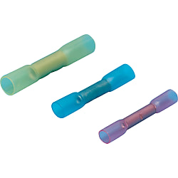
Insulated Crimp Terminal, Waterproof Crimp Ring [100 Pieces Per Package]
It is an equipment for connecting two wires together and comes in various sizes.
[Features]
• Compatible electric wire size (AWG): 22-20, 10 and 14
• Representative Standard: 11.5 and 15
• Insulation colors: Transparent yellow and translucent blue
• Insulation material: High density polyethylene
[Applications]
It is a equipment for connecting two wires together.

● A widely used, insulated and crimped-model ring that has been waterproofed. It can be adhered after the wires have been butt-joint crimped by heat-shrinking the insulator.

· Available from 1 pack (100 pieces).
· Almost all wires can be used, but the waterproofing effect is not available with the covering materials silicone rubber, glass fiber braid, fluoropolymer* (FET, TFE, etc.), and fluororubber.
· As it is heat-shrinkable, do not leave in places subject to direct sunlight or near heating equipment.
* fluoropolymer is a registered trademark for fluororesin made by DuPont (USA).
Specifications

| 1 Pack | 100-piece Pack |
| Model | Color |
| SB-2218 | Transparent Yellow |
| SB-1816 | Transparent Red |
| SB-1614 | Transparent Blue |
| SB-1210 | Transparent Yellow |
Features
● Crimp terminals are wire connection components that are used in a wide range of applications such as electrical engineering as well as domestic electrical appliances, measuring devices, FA control devices etc.● Available in 2 types: conventional type bare crimp terminals without insulation sheathing, and crimp terminals with insulation sleeves.
● We also offer products with JIS, UL and CSA certification, allowing for use with peace of mind.
Allowable Current
| Wire Size Used | Terminal Nominal Number | Allowable current or less (at 30°C) | ||||
|---|---|---|---|---|---|---|
| Single Wire | Stranded Wire | AWG | With rubber vinyl insulated wire | Cord | ||
| Single Wire | Stranded Wire | |||||
| - | 0.08 | 28 | 0.08 | - | - | - |
| - | 0.3 | 26, 24 | 0.3 | - | - | - |
| 0.8 | 0.3, 0.5 | 22, 20 | 0.5 | - | - | - |
| 1.0, 1.2 | 0.75, 0.9, 1.25 | 18, 16 | 1.25 | 16 A, 19 A | 16 A, 17 A, 19 A | 7 A (0.75 mm), 12 A |
| 1.6 | 2 | 14 | 2 | 27 A | 27 A | 17 A |
| 2.0 | 3.5 | 12 | 3.5 | 35 A | 37 A | 23 A |
| 2.6 | 5.5 | 10 | 5.5 | 48 A | 48 A | 35 A |
| 3.2 | 8 | 8 | 8 | 62 A | 62 A | - |
Allowable Voltage
Bare Crimp Terminal: 600 VAC or lessInsulated Crimp Terminal: 300 VAC or less
Materials
Conductor Component: Oxygen-free Copper (Tin-Plated)Insulator Component: Refer to product pages
Compatible Wire Size
Refer to product pages.Crimping Method

Diagram A

| Terminal Nominal (Note 3) | Wire Size Used | Wire Sheath Strip Dimensions (mm) | ||||
|---|---|---|---|---|---|---|
| Stranded Wire (mm2) | Single Wire (Dia. mm) | Wire Conjugation Capacity (Note 1) | L (Note 2) | L1 | L2 | |
| 0.08 | 0.08 | - | - | B + L1 + L2 | 0.5 ~ 2 | 0 ~ 1 |
| 1.25 | 0.3, 0.5, 0.75, 0.9, 1.25 | 0.75 ~ 1.44 | 0.25 ~ 1.65 | B + L1 + L2 | 0.5 ~ 2 | 0 ~ 1 |
| 2 | 1.25, 2.0 | 1.14 ~ 1.82 | 1.04 ~ 2.63 | B + L1 + L2 | 0.5 ~ 2 | 0 ~ 1 |
| 5.5 | 3.5, 5.5 | 1.82 ~ 2.89 | 2.63 ~ 6.64 | B + L1 + L2 | 0.5 ~ 2 | 0 ~ 1 |
| 8 | 8 | 2.89 ~ 3.65 | 6.64 ~ 10.52 | B + L1 + L2 | 1 ~ 2 | 0 ~ 2 |
(Note 2) The calculation method of the L dimension is simply for finding the dimensions of the wire sheath stripping, and is not used to indicate the shape or dimensions after crimping.
(Note 3) For applicable wires at 0.3, use a conductor cross-sectional area close to the terminal nominal. Furthermore, fold back the core wire when crimping thin types such as AWG28.
Also, ensure that the wire stripping dimension complies with the terminal nominal 1.25.
Crimping Guideline

Selection of Crimping Tool

Visual Inspection after Crimping
