Insulated Crimp Terminal, Exclusive Bar
Brand :
MISUMI
Caution
Product Description
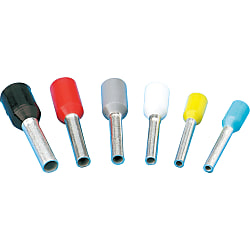
Cord-end sleeve (Single) [100 Pieces Per Package]
It is equipment used for connecting wires to a terminal to help prevent the wire from splitting and comes in various sizes.
[Features]
• Compatible electric wire size (AWG): 16, 18 and 20
• Compatible electric wire section area (mm²): 0.25, 0.34, 0.5, 0.75, 1 and 1.5
• Mounting hole diameter (mm.): 3.2, 3.7, 4.3, 5.3, 6.4 and 8.4
• The product supports the standard: DIN
• Insulation color: Red, white and black
[Applications]
This tool is used to connect wires to terminals in electrical maintenance tasks

● The bar terminal with a plastic insulating collar is made of soft electrolytic copper that has been tin-plated.
● The feature of this bar terminal is that when there is close contact at the connecting point, the insulation safety is enhanced and the stranded wire will not unravel.
● With a plastic insulating collar / Compliant with DIN46 228 Article 4

· This terminal is intended to bundle stranded wires into a single wire and is not designed to crimp fix electric wires and terminals strongly.
Specifications

| 1 Pack | 100-piece Pack |
Features
● Crimp terminals are wire connection components that are used in a wide range of applications such as electrical engineering as well as domestic electrical appliances, measuring devices, FA control devices etc.● Available in 2 types: conventional type bare crimp terminals without insulation sheathing, and crimp terminals with insulation sleeves.
● We also offer products with JIS, UL and CSA certification, allowing for use with peace of mind.
Allowable Current
| Wire Size Used | Terminal Nominal Number | Allowable current or less (at 30°C) | ||||
|---|---|---|---|---|---|---|
| Single Wire | Stranded Wire | AWG | With rubber vinyl insulated wire | Cord | ||
| Single Wire | Stranded Wire | |||||
| - | 0.08 | 28 | 0.08 | - | - | - |
| - | 0.3 | 26, 24 | 0.3 | - | - | - |
| 0.8 | 0.3, 0.5 | 22, 20 | 0.5 | - | - | - |
| 1.0, 1.2 | 0.75, 0.9, 1.25 | 18, 16 | 1.25 | 16 A, 19 A | 16 A, 17 A, 19 A | 7 A (0.75 mm), 12 A |
| 1.6 | 2 | 14 | 2 | 27 A | 27 A | 17 A |
| 2.0 | 3.5 | 12 | 3.5 | 35 A | 37 A | 23 A |
| 2.6 | 5.5 | 10 | 5.5 | 48 A | 48 A | 35 A |
| 3.2 | 8 | 8 | 8 | 62 A | 62 A | - |
Allowable Voltage
Bare Crimp Terminal: 600 VAC or lessInsulated Crimp Terminal: 300 VAC or less
Materials
Conductor Component: Oxygen-free Copper (Tin-Plated)Insulator Component: Refer to product pages
Compatible Wire Size
Refer to product pages.Crimping Method

Diagram A

| Terminal Nominal (Note 3) | Wire Size Used | Wire Sheath Strip Dimensions (mm) | ||||
|---|---|---|---|---|---|---|
| Stranded Wire (mm2) | Single Wire (Dia. mm) | Wire Conjugation Capacity (Note 1) | L (Note 2) | L1 | L2 | |
| 0.08 | 0.08 | - | - | B + L1 + L2 | 0.5 ~ 2 | 0 ~ 1 |
| 1.25 | 0.3, 0.5, 0.75, 0.9, 1.25 | 0.75 ~ 1.44 | 0.25 ~ 1.65 | B + L1 + L2 | 0.5 ~ 2 | 0 ~ 1 |
| 2 | 1.25, 2.0 | 1.14 ~ 1.82 | 1.04 ~ 2.63 | B + L1 + L2 | 0.5 ~ 2 | 0 ~ 1 |
| 5.5 | 3.5, 5.5 | 1.82 ~ 2.89 | 2.63 ~ 6.64 | B + L1 + L2 | 0.5 ~ 2 | 0 ~ 1 |
| 8 | 8 | 2.89 ~ 3.65 | 6.64 ~ 10.52 | B + L1 + L2 | 1 ~ 2 | 0 ~ 2 |
(Note 2) The calculation method of the L dimension is simply for finding the dimensions of the wire sheath stripping, and is not used to indicate the shape or dimensions after crimping.
(Note 3) For applicable wires at 0.3, use a conductor cross-sectional area close to the terminal nominal. Furthermore, fold back the core wire when crimping thin types such as AWG28.
Also, ensure that the wire stripping dimension complies with the terminal nominal 1.25.
Crimping Guideline

Selection of Crimping Tool

Visual Inspection after Crimping
