Stripped Crimp Terminal Round Model
Caution
Product Description
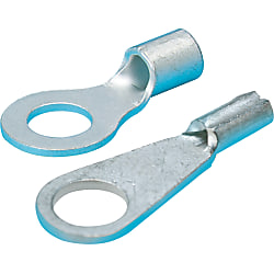
Stripped Crimp Terminal Round Model [15-1,000 Pieces Per Package]
There are many sizes to select from for this equipment, which is used for connecting wires to a terminal.
[Features]
• Compatible electric wire size (AWG): 28, 26-24, 22-16, 16-14, 12-10, 8, 6,4 and 2
• Compatible electric wire size (MCM): 250-300
• Compatible electric stranded wire size smallest/largest (mm²): 0.08 and 152.05
• Compatible electric single wire size smallest/largest (mm): 0.32 and 13.8
• Representative Standard: JIS (JQ0608003), UL (E74917), and CSA (LR66230)
[Applications]
It is used for connecting the wire and electric components.

● Our original and innovative 0.08-3 and 0.08-M3.5 can save 45% of wiring cost (our measurement value) by eliminating the need for wire folding.
● Most commonly used round model crimp terminals without insulation.
● JIS (JQ0608003), UL (E74917), and CSA (LR66230) certified high quality crimp terminals. 0.3-3 has UL certification only.
●80-10, 80-12, 80-14, and 80-16 have CSA and UL certification only.
● Operating temperature range is -40 to +90°C.

·Perform crimping with the dedicated crimping tools.
·Available from 1 pack (100 pieces) or by the box.
· Heat-resistant model (nickel plated product) is not available.
Specifications

Available as Box Products
| 1 Pack | 100-piece Pack |
| Model Number | Pack Product Quantity | Boxed Product Quantity |
| 0.08-3 | 100 Pieces | 1000 Pieces |
| 0.08-M3.5 | ||
| 0.3-3 | ||
| 1.25-3 | ||
| 1.25-M3.5 | ||
| 1.25-3.5 | ||
| 1.25-4 | ||
| 1.25-5 | ||
| 2-3.5 | ||
| 2-4 | ||
| 2-5 | ||
| 2-6 | 500 Pieces | |
| 2-8 | ||
| 5.5-4 | ||
| 5.5-5 | ||
| 5.5-6 | ||
| 5.5-8 | 400 Pieces | |
| 5.5-10 | ||
| 8-5 | ||
| 8-6 | ||
| 8-8 | 300 Pieces | |
| 8-10 | ||
| 14-5 | 200 Pieces | |
| 14-6 | ||
| 14-8 | ||
| 14-10 | ||
| 14-12-BOX | Pack Product Not Available | 100 Pieces |
| 22-6-BOX | ||
| 22-8-BOX | ||
| 22-10-BOX | ||
| 22-12-BOX | ||
| 38-8-BOX | 50 Pieces | |
| 38-10-BOX | ||
| 38-12-BOX | ||
| 60-8-BOX | ||
| 60-10-BOX | ||
| 60-12-BOX | ||
| 60-14-BOX | 40 Pieces | |
| 80-10-BOX | 25 Pieces | |
| 80-12-BOX | ||
| 80-14-BOX | ||
| 80-16-BOX | ||
| 100-10-BOX | ||
| 100-12-BOX | ||
| 100-14-BOX | 20 Pieces | |
| 100-16-BOX | ||
| 100-20-BOX | ||
| 150-10-BOX | 15 Pieces | |
| 150-12-BOX | ||
| 150-14-BOX | ||
| 150-16-BOX | ||
| 150-20-BOX |
Features
● Crimp terminals are wire connection components that are used in a wide range of applications such as electrical engineering as well as domestic electrical appliances, measuring devices, FA control devices etc.● Available in 2 types: conventional type bare crimp terminals without insulation sheathing, and crimp terminals with insulation sleeves.
● We also offer products with JIS, UL and CSA certification, allowing for use with peace of mind.
Allowable Current
| Wire Size Used | Terminal Nominal Number | Allowable current or less (at 30°C) | ||||
|---|---|---|---|---|---|---|
| Single Wire | Stranded Wire | AWG | With rubber vinyl insulated wire | Cord | ||
| Single Wire | Stranded Wire | |||||
| - | 0.08 | 28 | 0.08 | - | - | - |
| - | 0.3 | 26, 24 | 0.3 | - | - | - |
| 0.8 | 0.3, 0.5 | 22, 20 | 0.5 | - | - | - |
| 1.0, 1.2 | 0.75, 0.9, 1.25 | 18, 16 | 1.25 | 16 A, 19 A | 16 A, 17 A, 19 A | 7 A (0.75 mm), 12 A |
| 1.6 | 2 | 14 | 2 | 27 A | 27 A | 17 A |
| 2.0 | 3.5 | 12 | 3.5 | 35 A | 37 A | 23 A |
| 2.6 | 5.5 | 10 | 5.5 | 48 A | 48 A | 35 A |
| 3.2 | 8 | 8 | 8 | 62 A | 62 A | - |
Allowable Voltage
Bare Crimp Terminal: 600 VAC or lessInsulated Crimp Terminal: 300 VAC or less
Materials
Conductor Component: Oxygen-free Copper (Tin-Plated)Insulator Component: Refer to product pages
Compatible Wire Size
Refer to product pages.Crimping Method

Diagram A

| Terminal Nominal (Note 3) | Wire Size Used | Wire Sheath Strip Dimensions (mm) | ||||
|---|---|---|---|---|---|---|
| Stranded Wire (mm2) | Single Wire (Dia. mm) | Wire Conjugation Capacity (Note 1) | L (Note 2) | L1 | L2 | |
| 0.08 | 0.08 | - | - | B + L1 + L2 | 0.5 ~ 2 | 0 ~ 1 |
| 1.25 | 0.3, 0.5, 0.75, 0.9, 1.25 | 0.75 ~ 1.44 | 0.25 ~ 1.65 | B + L1 + L2 | 0.5 ~ 2 | 0 ~ 1 |
| 2 | 1.25, 2.0 | 1.14 ~ 1.82 | 1.04 ~ 2.63 | B + L1 + L2 | 0.5 ~ 2 | 0 ~ 1 |
| 5.5 | 3.5, 5.5 | 1.82 ~ 2.89 | 2.63 ~ 6.64 | B + L1 + L2 | 0.5 ~ 2 | 0 ~ 1 |
| 8 | 8 | 2.89 ~ 3.65 | 6.64 ~ 10.52 | B + L1 + L2 | 1 ~ 2 | 0 ~ 2 |
(Note 2) The calculation method of the L dimension is simply for finding the dimensions of the wire sheath stripping, and is not used to indicate the shape or dimensions after crimping.
(Note 3) For applicable wires at 0.3, use a conductor cross-sectional area close to the terminal nominal. Furthermore, fold back the core wire when crimping thin types such as AWG28.
Also, ensure that the wire stripping dimension complies with the terminal nominal 1.25.
Crimping Guideline

Selection of Crimping Tool

Visual Inspection after Crimping
