● The waterproof connectors CE05 and JL04V are certified as products that conform to the connector standard "DIN VDE0627" and have obtained T¨UV Rheinland certification, which is an EU (European Union) approved certification agency.
● Certification obtained from the US UL standard "UL-1977".
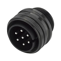
● When coupled, they demonstrate waterproofing and dustproofing of IP67 class and prevent the intrusion of water drops, cutting oil, dust, etc., from outside.
● The connector is compatible with MIL-C-5015 and conventional MS connectors.
● There are 4 kinds of connectors
○ Straight Connectors
○ Angle Connectors
○ Conduit Dedicated Connectors
○ Panel Mount
● Each connector is solder connection type and allows work without dedicated tools.
CE05/JL04V European Standard/Waterproof Conduit Mount Plug (Screw)
Brand :
MISUMI
Caution
Product Description
Used By Fastening Onto Conduit

● A conduit mounting model used by mounting the conduit (wire protection tube) on the cable lead side. The unconnected back shell does not take up space when connected to the conduit.
It has waterproof fitting structure class IP67, which makes it suitable for use in places exposed to water or dust.
● It can be connected with the panel mounting model.

· Use by combining with the conduits offered by MISUMI.
Metal conduit (MSA, MAA series)
Specifications

| Series Name | Model | Contact Shape | Number of Cores | Arrangement No. | Shell Size | Weight |
| CE05 Series | CE05-6A18-10PD-D | Male | 4 | 18-10 | 18 | 33.4 |
| CE05-6A20-4PD-D | 4 | 20-4 | 20 | 36.1 | ||
| CE05-6A20-15PD-D | 7 | 20-15 | 39 | |||
| CE05-6A22-22PD-D | 4 | 22-22 | 22 | 50.8 | ||
| CE05-6A22-23PD-D | 8 | 22-23 | 46.7 | |||
| CE05-6A32-17PD-D | 4 | 32-17 | 32 | 151.2 | ||
| CE05-6A10SL-3SC-D | Female | 3 | 10SL-3 | 10SL | 11.7 | |
| CE05-6A14S-2SD-D | 4 | 14S-2 | 14S | 20.2 | ||
| CE05-6A18-10SD-D | 4 | 18-10 | 18 | 45.5 | ||
| CE05-6A18-12SD-D | 6 | 18-12 | 46.5 | |||
| CE05-6A20-4SD-D | 4 | 20-4 | 20 | 52.1 | ||
| CE05-6A20-15SD-D | 7 | 20-15 | 55.8 | |||
| CE05-6A20-18SDE-D | 9 | 20-18 | 58.3 | |||
| CE05-6A22-22SD-D | 4 | 22-22 | 22 | 71.3 | ||
| CE05-6A22-23SD-D | 8 | 22-23 | 68.5 | |||
| CE05-6A24-10SD-D | 7 | 24-10 | 24 | 92.5 | ||
| CE05-6A24-10SG-D | 7 | 24-10 (G) | 92.5 | |||
| CE05-6A24-11SGH-D | 9 | 24-11 | 88.8 | |||
| CE05-6A32-17SD-D | 4 | 32-17 | 32 | 141.5 | ||
| JL04V Series | JL04V-6A18-10SE-R | Female | 4 | 18-10 | 18 | 39 |
| JL04V-6A18-12SE-R | 6 | 18-12 | 18 | 39 | ||
| JL04V-6A20-4SE-R | 4 | 20-4 | 20 | 42 | ||
| JL04V-6A22-22SE-R | 4 | 22-22 | 22 | 63 | ||
| JL04V-6A22-23SE-R | 8 | 22-23 | 22 | 62 | ||
| JL04V-6A24-10SE-R | 7 | 24-10 | 24 | 81 | ||
| JL04V-6A24-10SEG-R | 7 | 24-10(G) | 24 | 200 | ||
| JL04V-6A24-11SE-R | 9 | 24-11 | 24 | 81 | ||
| JL04V-6A28-11SE-R | 22 | 28-11 | 28 | 100 |
Protection Circuit Connection Structural Diagram

Protection circuit connection structure is used. When coupling, the incorporated earth terminal makes contact before the other contacts, and at the time of removal, the earth terminal is disconnected after the other contacts, so the unit circuits are protected reliably.
Material / Finish
| Item | Materials | Finish | |
|---|---|---|---|
| Shell (Body) | Aluminum Alloy | Zinc-plated Black Chromate Treatment | |
| Insulator | Panel Mount Male Front Side | Silicone Rubber | Black |
| Panel Mount Male Rear Side | Synthetic Resin (UL94V-0) | ||
| Male Connector Front / Rear Side | |||
| Female Front / Rear Side | |||
| Contact | Copper Alloy | Silver Plating | |
| Gasket (Connector Portion) | Nitrile Rubber | Black | |
| O-ring Gasket (Back Shell Portion) | Nitrile Rubber | Black | |
| Retainer Ring | Copper Alloy | Trivalent Black Chromate Treatment | |
| Coupling Nut | Aluminum Alloy (JL04V is Steel) | Trivalent Black Chromate Treatment | |
| Earth Lug | Copper Alloy | Silver Plated (JL04V is Nickel Plated) | |
| Cable Clamp | Aluminum Alloy | Trivalent Black Chromate Treatment | |
| Rubber Bushing | Chloroprene Rubber (JL04V Nitrile Rubber) | Black | |
| Rear Gasket (Note 1) | Silicone Rubber | Black | |
(Note 1) Flange gasket is not included with JL04V-2A28-11PE.

Electrical Properties
| Item | Characteristics | |||
|---|---|---|---|---|
| Contact Size | Current | |||
| Rated Current (Per 1 Contact) | #4 | 80 A or lower | ||
| #8 | 46 A or lower | |||
| #12 | 23 A or lower | |||
| #16 | 13 A or lower | |||
| Rated Voltage | Refer to Contact Arrangement Table | |||
| Withstand Voltage | Refer to Contact Arrangement Table | |||
| Insulation Resistance | 5,000 MΩ or more at 500 VDC | |||
| Contact Resistance (Steady-state Level, Initial) | Contact Size | Compatible Wire Size (AWG) | Test Current Amps | Contact Resistance mΩ or less |
| #4 | 4 | 80 | 1 | |
| 6 | 60 | 1 | ||
| 8 | 46 | 1 | ||
| #8 | 8 | 57 | 2 | |
| 10 | 46 | 2 | ||
| 12 | 33 | 2 | ||
| #12 | 12 | 23 | 2 | |
| 14 | 17 | 3 | ||
| 16 | 13 | 4 | ||
| #16 | 16 | 13 | 4 | |
| 18 | 10 | 7 | ||
| 20 | 7.5 | 8 | ||
| 22 | 5 | 15 | ||
| 24 | 3 | 15 | ||
Compatible Wire
| Contact | Applicable Electric Wire | ||
|---|---|---|---|
| Size | Minimum Solder Cup Inner Diameter (Note 2) | Conductor Cross-sectional Area | AWG Size |
| #4 | φ7.5 mm | 22.0 mm2 | #6 ~ #4 |
| #8 | φ4.7 mm | 8.0 mm2 | #10 ~ #8 |
| #12 | φ2.7 mm | 3.5 mm2 | #14 ~ #12 |
| #16 | φ1.76 mm | 1.25 mm2 | #22 ~ #16 |
(Note 2) Minimum solder cup internal diameter is the size of the CE05 connector
Mechanical Properties
| Operating Temperature Range | -55°C ~ +125°C |
|---|---|
| Waterproofing | IP67 Equivalent |
| Airtightness (Panel Mount Male) (Note 3) | 2.9 x 10⁴ Pa (0.3 kgf/cm2), 1 minute |
| Service Life | 500 Insertions and Removals |
(Note 3) Except JL04V-2A28-11PE
Panel Cut Size Drawing

| Compatible Shell Size | φA (mm) | φB (mm) +0.2 -0 | C (mm) |
|---|---|---|---|
| 10SL | 19.0 | 3.1 | 18.26 |
| 14S | 24.0 | 3.1 | 23.01 |
| 18 | 30.2 | 3.1 | 26.97 |
| 20 | 33.4 | 3.1 | 29.36 |
| 22 | 36.6 | 3.1 | 31.75 |
| 24 | 39.7 | 3.8 | 34.92 |
| 28 | 46.1 ±0.5 | 3.8 | 39.67 ±0.13 |
| 32 | 51.0 | 4.5 | 44.45 |
Combination Method

Contact Arrangement Table
