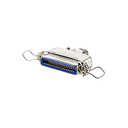
Centronics Solder Spring-lock Connector (Female)
Brand :
MISUMI
Caution
Product Description
[Features]A Centronics connector for relay with a lineup of low-priced products. This connector is used for wire-to-wire connection with a male connector by attaching cable with solder.

● Connectors for use in relay connections with male connectors after first mounting the cables with solder.

· It can also be connected with the pressure weld models.
· It cannot be connected with the screw lock model on.
Specifications

| Model Number | Number of Cores | A | B | C | D | E |
| 57-60140 | 14 | 43.9 | 36.0 | 12.96 | 32.5 | 6.5 x 9.8 |
| 57-60240 | 24 | 54.7 | 46.8 | 23.75 | 32.1 | 11.1 x 9.8 |
| 57-60360 | 36 | 67.7 | 59.7 | 36.70 | 34.1 | 13.9 x 9.8 |
| 57-60500 | 50 | 82.8 | 74.9 | 51.82 | 36.5 | 17.0 x 9.8 |
| Model Number | Number of Cores | A | B | C | D | E |
| RC-60140 | 14 | 43.9 | 36.0 | 12.96 | 31.6 | Ø7.0 |
| RC-60240 | 24 | 55.0 | 46.8 | 23.76 | 30.1 | Ø9.0 |
| RC-60360 | 36 | 67.7 | 59.7 | 36.72 | 32.7 | Ø11.5 |
| RC-60500 | 50 | 82.8 | 74.9 | 51.84 | 35.5 | Ø12.5 |
Drawing

Material / Finish
Soldering Type, Gender Changer
| Item | Materials | Finish |
|---|---|---|
| Insulator (RC Type) | Glass-Filled Polybutylene Terephthalate | UL94V-0, Blue |
| Insulator (Type 57, Angle Type) | DAP Resin | UL94V-0, Blue |
| Contact | Copper Alloy | Nickel Base Gold Plating |
| Shell | Steel | Nickel-plated |
| Hood (Angle Type Only) | Aluminum Alloy | Rustproofing Treatment |
| Spring Latch | Stainless Steel | - |
Soldering Type

Pressure Welding Type
| Item | Materials | Finish |
|---|---|---|
| Insulator | PC Resin | UL94V-0, Blue |
| Contact | Copper Alloy | Nickel Base Gold Plating |
| Shell (57FE-40 only) | Brass | Nickel-plated |
| Strain Relief | PC Resin | UL94V-0, Blue |
| Earth Plate (57FE-30 only) | Brass | Nickel-plated |
| Spring Latch (57FE-40 only) | Stainless Steel | - |
| Metal Hood (57FE-30 only) | Aluminum Alloy | Rustproofing Treatment |
Pressure Welding Type

* 57F series is made up of 4 components: insulator, contact, strain relief, and pressure welding cover.
Compatible Wire
| Connector Type | Single Wire Conductor Diameter | Stranded Wire Conductor Cross-sectional Area | AWG Size |
|---|---|---|---|
| Soldering Type | 0.65 mm or less | 0.2 mm2 or less | Stranded Wire AWG24 or less Single Wire AWG22 or less |
| Pressure Welding Type | - | - | AWG26 (Single Wire), AWG28 (Stranded Wire, Single Wire) or AWG30 (Single Wire) 1.27 mm Pitch Flat Cable |
Electrical Properties
| Item | Soldering Type | Pressure Welding Type |
|---|---|---|
| Rated Current | 5 A or lower | 1 A or lower |
| Rated Voltage | 500 VAC or less | 250 VAC or less |
| Contact Resistance | 35 mΩ or less / 1 ADC | 35 mΩ or less / 1 ADC |
| Insulation Resistance | 1,000 MΩ or more / 500 VDC | 1,000 MΩ or more / 500 VDC |
| Withstand Voltage | 1,000 VAC / minute | 500 VAC / minute |
| Operating Temperature Range | -55°C ~ +105°C | -55°C ~ +105°C |
Mechanical Properties
| Item | Characteristics | Conditions |
|---|---|---|
| Insertion and Extraction Force Per Single Pole | Insertion Force: 112 g or less, Extraction Force: 86 g or less | When the plug and socket are inserted and extracted, the total extraction force is divided by each core number to convert into force per single pole |
| Vibration Resistance | · No interruption to power supplies of 1 μs or more · No abnormalities such as damage etc. on the connector | In compliance with MIL-STD-202 test method condition 204 A, simple vibration with smaller amplitude, either the total amplitude of 1.52 mm from 10 Hz to 500 Hz or 10 G (gravity units) is applied to each for 3 hours in mutually perpendicular 3-axis direction. |
| Impact Resistance | No cracks in the connector or abnormalities such as loosening in breakable parts | Impact of 50 G with duration 11 msec is applied to the coupled connector in mutually perpendicular axis direction. |
| Insertion and Removal Durability | No mechanical damage | Perform insertion and removal 500 times at speeds not exceeding 500 times per 1 hour. |
Environmental Properties
| Item | Characteristics | Conditions |
|---|---|---|
| Temperature Resistance | There should be no physical damage or obstacle when inserting or removing the connector | Repeatedly expose to temperatures +85°C and -55°C for 30 minutes 5 times each. However, do not expose to room temperature for 5 minutes or more when moving from low temperature to high and from high temperature to low. |
| Humidity Resistance | · There should be no mechanical damages · Voltage Resistance 300 VAC 1 minute | Perform 96-hour humidity test with the connector detached in compliance with MIL-STD-202 test method 103 B. |
| Corrosion Resistance | There should be no significant corrosion or obstacle when inserting or removing the connector | After performing a 48-hour salt spray test with the connector attached in compliance with MIL-STD-202 test method condition 101 B, the connector is uncoupled, washed, and dried for 12 hours in a drying oven at 38°C. |
Contact Arrangement Diagram

This diagram is a view of the socket (female) connector from the coupling.
The plug (male) will be reversed on the left and right.