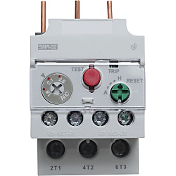
Thermal Relay
Brand :
MISUMI
Caution
Product Description
- Thermal Relay for Mini Contact SMR series
- Part number for series including SMR-12, SMR-32, and SMR-63.
- Thermal Overload relays enhance electrical safety by monitoring motor currents. If currents exceed safe levels, the relay triggers protective actions, preventing motor overheating and potential fire hazards.
- current Auxiliary contact: 1NO+1NC.
- Certified Standards: CE
- Protection Class (IEC60529): IP20
- Rated Frequency: 50/ 60 Hz
- Switching reset: Automatic reset and Manual Reset
- Rated Current: 5 A.
- Operating Temperature Range: -25 to 55°C

● Thermal relay sold individually at a very low price.
● This CE Marking compliant product has passed certification testing.
● Terminal cover is standard equipment.

· When you select a thermal relay, please check the frame size (AF) of the combined electromagnetic contactor.
· There are 2 heaters.
Specifications

| Electromagnetic Contactor Frame Size (AF) | Motor Capacity (KW) | Setting Range (A) | Model |
| 18 | 0.05 | 0.4 ~ 0.63 | SMR-12-0.52 |
| 0.1 | 0.63 ~ 1 | SMR-12-0.82 | |
| 0.2 | 1 ~ 1.6 | SMR-12-1.3 | |
| 0.4 | 1.6 ~ 2.5 | SMR-12-2.1 | |
| 0.75 | 2.5 ~ 4 | SMR-12-3.3 | |
| 1 | 4 ~ 6 | SMR-12-5 | |
| 1.5 | 5 ~ 8 | SMR-12-6.5 | |
| 1.5 | 6 ~ 9 | SMR-12-7.5 | |
| 2.2 | 7 ~ 10 | SMR-12-8.5 | |
| 22/40 | 0.05 | 0.4 ~ 0.63 | SMR-32-0.52 |
| 0.1 | 0.63 ~ 1 | SMR-32-0.82 | |
| 0.2 | 1 ~ 1.6 | SMR-32-1.3 | |
| 0.4 | 1.6 ~ 2.5 | SMR-32-2.1 | |
| 0.75 | 2.5 ~ 4 | SMR-32-3.3 | |
| 1 | 4 ~ 6 | SMR-32-5 | |
| 1.5 | 5 ~ 8 | SMR-32-6.5 | |
| 1.5 | 6 ~ 9 | SMR-32-7.5 | |
| 2.2 | 7 ~ 10 | SMR-32-8.5 | |
| 3.7 | 9 ~ 13 | SMR-32-11 | |
| 3.7 | 12 ~ 18 | SMR-32-15 | |
| 5.5 | 16 ~ 22 | SMR-32-19 | |
| 5.5 | 18 ~ 25 | SMR-32-21.5 | |
| 7.5 | 22 ~ 32 | SMR-32-27 | |
| 65 | 3.7 | 12 ~ 18 | SMR-63-15S |
| 5.5 | 16 ~ 22 | SMR-63-19S | |
| 5.5 | 18 ~ 25 | SMR-63-21.5S | |
| 7.5 | 24 ~ 36 | SMR-63-30S | |
| 7.5 | 28 ~ 40 | SMR-63-34S | |
| 11 | 34 ~ 50 | SMR-63-42S | |
| 15 | 45 ~ 65 | SMR-63-55S |
Example
Method of Indicator and Trip Test in Operating ConditionsThe operating status of the thermal relay can be judged by the following indicator.
In addition, trip test can be performed by pulling the red test button.

Operation of Test Button
1) Operation When Pressed
The circuit configuration can be checked when the test button is pressed.
It works only as long as the button is pressed.
(For example, contact b will be OFF only while it is being pressed)
Operation When Pulled
2) When pulled, the operation of the trip can be checked
Orange is displayed on the trip indicator, and it enters into the trip state.
If reset is set manually, it can be reset by pressing the reset button.
If it is set to automatic, it will reset automatically.
If you perform the trip test by pulling, please first open the transparent resin cover of the thermal relay.
(It does not correctly trip if pulled while closed)

