Insulation Exclusive Bar Crimping Terminal (Ferrule Terminal)
Brand :
MISUMI
Caution
Product Description
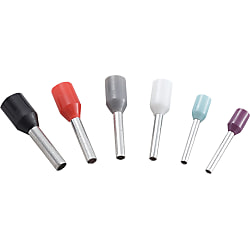
Insulation Exclusive Bar Crimping Terminal (Ferrule Terminal) [100 Pieces Per Package]
There are many sizes of this equipment available for connecting wires to a terminal.
[Features]
• Compatible electric wire size (AWG): 14, 16 (1 wire/ 2 wires), 18, 20, 22, 24 and 26
• The product supports the standard: UL and DIN 46228
• Insulation color: Red, white, black and purple
[Applications]
This tool is used to connect wires to terminals in electrical maintenance tasks.

● MTR series! Low Cost and High Quality Insulation Dedicated Bar Model Terminal for FA

· Perform crimping with the dedicated crimping tools.
· Available as 1 pack (100 pieces).
· This terminal is intended to bundle stranded wires into a single wire and is not designed to crimp fix electric wires and terminal strongly.
Specifications

External Dimensions Table and Applicable Wires
| 1 Pack | 100-piece Pack |
| Model Number | Section Area mm2 | AWG | Number of Wire Plugs | Size (mm) | Insulation Material | Operating Temperature Range | Insulation Color | Compatible Tool | |||||
| A | B Terminal Length | C | D | E | F | ||||||||
| MFL25-5BE | 0.25 | 26 | 1 Piece | 9.4 | 5 | 4.4 | 1.1 | 0.8 | 1.9 | Nylon | +105°C | Light Blue | MTR-TOOL-E |
| MFL35-5TQ | 0.34 | 24 | Blue Green | ||||||||||
| MFL50-5WH | 0.50 | 22 | 11.0 | 6.0 | 1.3 | 1.0 | 2.6 | White | |||||
| MFL75-5GY | 0.75 | 20 | 11.3 | 6.3 | 1.5 | 1.2 | 2.8 | Gray | |||||
| MTRE0.25-8VI | 0.25 | 26 | 12.4 | 8 | 4.4 | 1.1 | 0.8 | 1.9 | Purple | ||||
| MTRE0.34-8TQ | 0.34 | 24 | Blue Green | ||||||||||
| MTRE0.5-8WH | 0.50 | 22 | 14.0 | 6.0 | 1.3 | 1.0 | 2.6 | White | |||||
| MTRE0.75-8GY | 0.75 | 20 | 14.3 | 6.3 | 1.5 | 1.2 | 2.8 | Gray | |||||
| MTRE1.0-8RD | 1.00 | 18 | 1.7 | 1.4 | 3.0 | Red | |||||||
| MTRE1.5-8BK | 1.50 | 16 | 2.0 | 1.7 | 3.5 | Black | |||||||
| MTFL75-8GY | 16 x 2 | 2 Pieces | 14.7 | 6.7 | 5.5 | Gray | |||||||
Product Drawings

Features
● Crimp terminals are wire connection components that are used in a wide range of applications such as electrical engineering as well as domestic electrical appliances, measuring devices, FA control devices etc.● Available in 2 types: conventional type bare crimp terminals without insulation sheathing, and crimp terminals with insulation sleeves.
● We also offer products with JIS, UL and CSA certification, allowing for use with peace of mind.
Allowable Current
| Wire Size Used | Terminal Nominal Number | Allowable current or less (at 30°C) | ||||
|---|---|---|---|---|---|---|
| Single Wire | Stranded Wire | AWG | With rubber vinyl insulated wire | Cord | ||
| Single Wire | Stranded Wire | |||||
| - | 0.08 | 28 | 0.08 | - | - | - |
| - | 0.3 | 26, 24 | 0.3 | - | - | - |
| 0.8 | 0.3, 0.5 | 22, 20 | 0.5 | - | - | - |
| 1.0, 1.2 | 0.75, 0.9, 1.25 | 18, 16 | 1.25 | 16 A, 19 A | 16 A, 17 A, 19 A | 7 A (0.75 mm), 12 A |
| 1.6 | 2 | 14 | 2 | 27 A | 27 A | 17 A |
| 2.0 | 3.5 | 12 | 3.5 | 35 A | 37 A | 23 A |
| 2.6 | 5.5 | 10 | 5.5 | 48 A | 48 A | 35 A |
| 3.2 | 8 | 8 | 8 | 62 A | 62 A | - |
Allowable Voltage
Bare Crimp Terminal: 600 VAC or lessInsulated Crimp Terminal: 300 VAC or less
Materials
Conductor Component: Oxygen-free Copper (Tin-Plated)Insulator Component: Refer to product pages
Compatible Wire Size
Refer to product pages.Crimping Method

Diagram A

| Terminal Nominal (Note 3) | Wire Size Used | Wire Sheath Strip Dimensions (mm) | ||||
|---|---|---|---|---|---|---|
| Stranded Wire (mm2) | Single Wire (Dia. mm) | Wire Conjugation Capacity (Note 1) | L (Note 2) | L1 | L2 | |
| 0.08 | 0.08 | - | - | B + L1 + L2 | 0.5 ~ 2 | 0 ~ 1 |
| 1.25 | 0.3, 0.5, 0.75, 0.9, 1.25 | 0.75 ~ 1.44 | 0.25 ~ 1.65 | B + L1 + L2 | 0.5 ~ 2 | 0 ~ 1 |
| 2 | 1.25, 2.0 | 1.14 ~ 1.82 | 1.04 ~ 2.63 | B + L1 + L2 | 0.5 ~ 2 | 0 ~ 1 |
| 5.5 | 3.5, 5.5 | 1.82 ~ 2.89 | 2.63 ~ 6.64 | B + L1 + L2 | 0.5 ~ 2 | 0 ~ 1 |
| 8 | 8 | 2.89 ~ 3.65 | 6.64 ~ 10.52 | B + L1 + L2 | 1 ~ 2 | 0 ~ 2 |
(Note 2) The calculation method of the L dimension is simply for finding the dimensions of the wire sheath stripping, and is not used to indicate the shape or dimensions after crimping.
(Note 3) For applicable wires at 0.3, use a conductor cross-sectional area close to the terminal nominal. Furthermore, fold back the core wire when crimping thin types such as AWG28.
Also, ensure that the wire stripping dimension complies with the terminal nominal 1.25.
Crimping Guideline

Selection of Crimping Tool

Visual Inspection after Crimping
