E-DHAS Series Full-Function AC Servo Driver

Brand :
MISUMI
Caution
- Since the battery kit E-AAS-BATBOX has not yet been released, it cannot be used with Absolute. Please contact us for information regarding the kit's release date.
Product Description
MISUMI AC Servo Motor which is applicable E-MASS2 and E-MASH2 and E-MASH1 Motors.
Related Materials
MISUMI Driver EDrive Debugging Software Click here to download now
MISUMI Driver Quick Start Manual. Click to Download:
>> E-DHASxxE-F (EtherCAT type)
>> E-DHASxxP-F ( Pulse + RS485 type)
MISUMI Driver Product Manual. Click to Download:
>> E-DHAS_E-F (EtherCAT type)
>> E-DHAS_P-F ( Pulse + RS485 type)
>>Power Cable / Encoder Cable / Debuggin Cable / Battery Kit
I/O Cables For MISUMI Driver
>>IO Cable
STO Function Cable
MISUMI Driver Quick Start Manual. Click to Download:
>> E-DHASxxE-F (EtherCAT type)
>> E-DHASxxP-F ( Pulse + RS485 type)
MISUMI Driver Product Manual. Click to Download:
>> E-DHAS_E-F (EtherCAT type)
>> E-DHAS_P-F ( Pulse + RS485 type)
Related Products
Cables For MISUMI Servo Motors and Driver>>Power Cable / Encoder Cable / Debuggin Cable / Battery Kit
I/O Cables For MISUMI Driver
>>IO Cable
STO Function Cable
Servo Driver Symbol Description
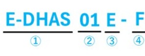
1.For the use of Incremental Encoders
| Part Number | ①Type | ②Rated Power (W) | ③Control Type | ④Driver Spec | Remark |
| E-DHAS01P-F | E-DHAS | 01: 100W | P: Pulse+RS485 Bus | F: Full-Function | Battery is not required |
| E-DHAS04P-F | 04: 400W | ||||
| E-DHAS08P-F | 08: 750W | ||||
| E-DHAS10P-F | 10: 1000W | ||||
| E-DHAS01E-F | 01: 100W | E: EtherCAT Bus | |||
| E-DHAS04E-F | 04: 400W | ||||
| E-DHAS08E-F | 08: 750W | ||||
| E-DHAS10E-F | 10: 1000W |
2.For the use of Absolute Encoder ( Battery Kit E-AAS-BATBOX needs to be purchased )
| Part Number | ①Type | ②Rated Power (W) | ③Control Type | ④Driver Spec | Remark |
| E-DHAS01P-F | E-DHAS | 01: 100W | P: Pulse+RS485 Bus | F: Full-Function | Battery Kit is required E-AAS-BATBOX |
| E-DHAS04P-F | 04: 400W | ||||
| E-DHAS08P-F | 08: 750W | ||||
| E-DHAS10P-F | 10: 1000W | ||||
| E-DHAS01E-F | 01: 100W | E: EtherCAT Bus | |||
| E-DHAS04E-F | 04: 400W | ||||
| E-DHAS08E-F | 08: 750W | ||||
| E-DHAS10E-F | 10: 1000W |
Differences in Driver Types
| Part number | E-DHAS□□P-F | E-DHAS□□E-F |
| Shape | Pulse | EtherCAT |
| Input Voltage | Single-phase/Three-phase 200 V to 240 V, ±10%, 50/60 Hz | |
| Max. Output current | Maximum current 21 A; Rated current 7 A | |
| Pulse Input | Support | Not supported |
| EtherCAT | Not supported | Support |
| Auto Tuning | Support | |
| Gantry Synchronization | Support | |
| Position Comparison | Support | |
| STO | Support | |
Dimensional Drawings
(Unit: mm)
100W & 400W 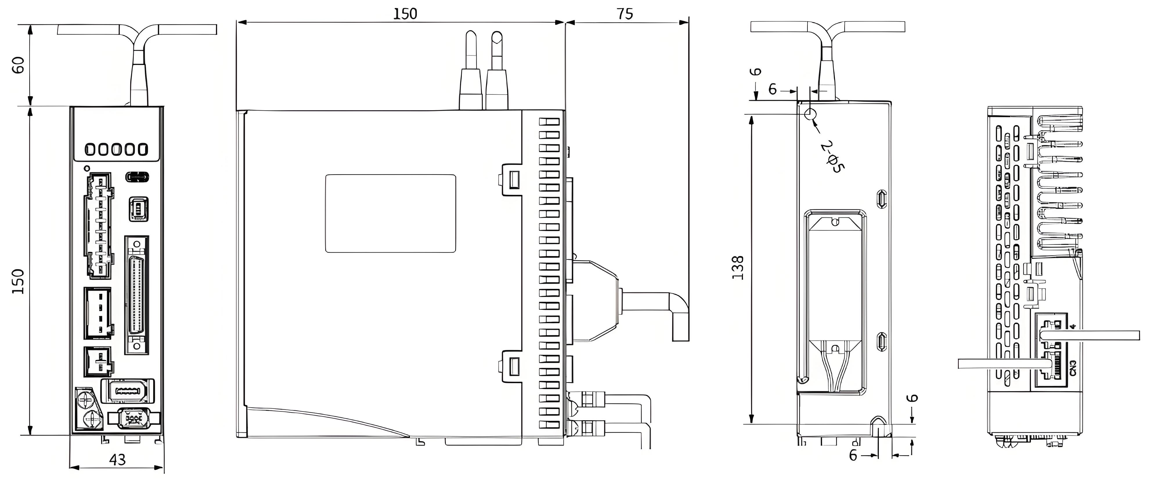
750W & 1000W100W & 400W

E-DHAS01P(E), E-DHAS04P(E)
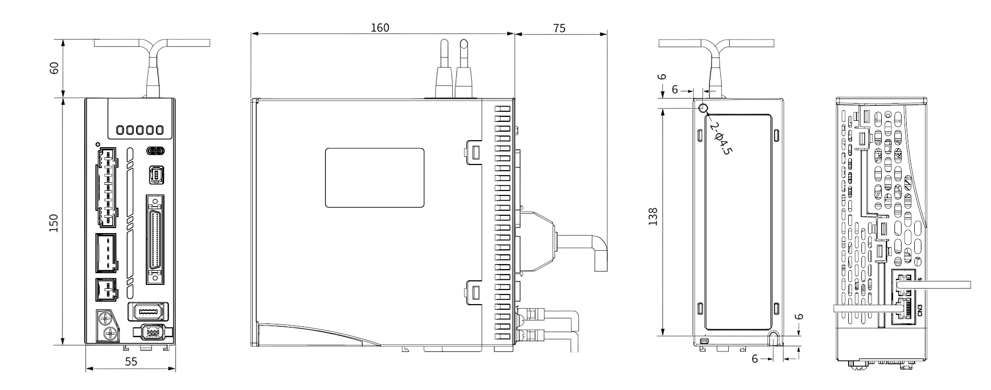
E-DHAS08P(E), E-DHAS10P(E)
Specification Table
| Driver Model | E-DHAS01P-F | E-DHAS04P-F | E-DHAS08P-F | E-DHAS10P-F | E-DHAS01E-F | E-DHAS04E-F | E-DHAS08E-F | E-DHAS10E-F |
| Rated Power (W) | 100 | 400 | 750 | 1000 | 100 | 400 | 750 | 1000 |
| Rated Output Current (Arms) | 1.2 | 2.8 | 5.5 | 7.0 | 1.2 | 2.8 | 5.5 | 7.0 |
| Maximum Output Current (Arms) | 4.8 | 9.3 | 16.9 | 21.0 | 4.8 | 9.3 | 16.9 | 21.0 |
| Regenerative Braking Resistance value (Ω) | 100 | 100 | 100 | 100 | - | 100 | 100 | 100 |
| Regenerative Braking Power of resistor (W) | 50 | 50 | 50 | 50 | - | 50 | 50 | 50 |
| Regenerative Braking Resistor Function | All models come with a built-in regenerative braking resistor and also support external braking resistors. | |||||||
| Cooling Method | Natural Cooling | Fan Cooling | Natural Cooling | Fan Cooling | ||||
Accessory Information
| Motor Part Number | Standard Compatible with Pulse Driver ( Driver Type) | Standard compatible with EtherCAT bus driver ( Driver Type) | Motor Flange Dimension (mm) | Power (W) | Electromagnetic Brake | Power Voltage |
| E-MAS□2-0401 E-MAS□2-04A5 | E-DHAS01P-F (Full Function) E-DFAS01P (Standard Function) | E-DHAS01E-F (Full Function) E-DFAS01E (Standard Function) | 40 | 100 | Not Provided | AC220V |
| E-MAS□2-0401B E-MAS□2-04A5B | Provided | |||||
| E-MAS□2-0602 | E-DHAS04P-F (Full Function) E-DFAS04P (Standard Function) | E-DHAS04E-F (Full Function) E-DFAS04E (Standard Function) | 60 | 200 | Not Provided | |
| E-MAS□2-0602B | Provided | |||||
| E-MAS□2-0604 | 400 | Not Provided | ||||
| E-MAS□2-0604B | Provided | |||||
| E-MAS□2-0808 | E-DHAS08P-F (Full Function) E-DFAS08P (Standard Function) | E-DHAS08E-F (Full Function) E-DFAS08E (Standard Function) | 80 | 750 | Not Provided | |
| E-MAS□2-0808B | Provided | |||||
| E-MAS□2-0810 | E-DHAS10P-F (Full Function) E-DFAS10P (Standard Function) | E-DHAS10E-F (Full Function) E-DFAS10E (Standard Function) | 1000 | Not Provided | ||
| E-MAS□2-0810B | Provided |
Connection Diagram

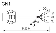
Debugging Cable

Model: E-CASTC2M Length: 2 m
No need to connect to a power supply—simply connect the driver and computer with a debugging cable,
and you can use the EDrive debugging software to monitor and modify parameters.
CN1 Control Cable
To select this product-> Go to Control Cable Products
E-DHAS□□P-F
For Pulse Type Use

Model No.: E-SCSI-50PIN-1
SCSI 50PIN Terminal Pin Functions
 | Pin | Pin Definition | Default Function | Function Description | Pin | Pin Definition | Default Function | Function Description |
| 1 | PUL +24 | Pulse Command Input | Low-speed pulse/direction command input method: PUL+ and PUL-: 5V differential input (500KHz) DIR+ and DIR-: 5V differential input (500KHz) PUL+24 and PUL-: 24V single-ended input (200KHz) DIR+24 and DIR-: 24V single-ended input (200KHz) | 37 | DO3+ | ALM+ | Servo Alarm Output | |
| 3 | PUL + | 36 | DO3- | ALM- | ||||
| 4 | PUL - | 39 | DO4+ | INP1+ | In-position Output | |||
| 2 | DIR +24 | Direction Command Input | 38 | DO4- | INP1- | |||
| 5 | DIR + | 41 | DOCOM | Output | General-purpose output common (Maximum current: 50mA, Maximum voltage: 30V) | |||
| 6 | DIR - | 12 | DO5 | ZSP | Zero Speed Detection Output | |||
| 44 | PULSH+ | High-speed Pulse Command Input | 4MHz high-speed pulse command input, 5V differential input | 40 | DO6 | TLC | Torque limit active output | |
| 45 | PULSH- | High-speed Pulse Command Input | 14 | Analog input 1 | AI1 | Speed command or speed limit input positive (0 to ±10 V) | ||
| 46 | SIGNH+ | High-Speed Direction Command Input | 4MHz high-speed direction command input, 5V differential input | 15 | GND | GND | Analog Ground | |
| 47 | SIGNH- | High-Speed Direction Command Input | 16 | Analog input 2 | AI2 | Torque command / positive torque limit input (0 to +10 V) | ||
| 13 | GND | GND | Internal ground | 17 | GND | GND | Analog Ground | |
| 7 | DI-COM | Input | General-purpose input common | 18 | Analog input 3 | AI3 | Torque command / negative torque limit input (–10 to 0 V) | |
| 8 | DI1 | NOT | Reverse drive prohibit input | 42 | AO1 | IM | Analog Monitor Output 1 (Configurable Monitoring Signal) | |
| 9 | DI2 | POT | Forward drive prohibit input | 43 | AO2 | SP | Analog Monitor Output 2 (Configurable Monitoring Signal) | |
| 26 | DI3 | No configuration | Not Provided | 21 | A+ | Differential Output | Encoder frequency dividing output phase A | |
| 27 | DI4 | GAIN | Gain switching input | 22 | A- | Differential Output | ||
| 28 | DI5 | DIV1 | Command pulse multiplier switching input | 48 | B+ | Differential Output | Encoder frequency dividing output phase B | |
| 29 | DI6 | SRV-ON | Servo enable ON input | 49 | B- | Differential Output | ||
| 30 | DI7 | CL | Deviation counter clear input | 23 | Z+ | Differential Output | Encoder frequency dividing output phase phase Z | |
| 31 | DI8 | A-CLR | Alarm Clear Input | 24 | Z- | Differential Output | ||
| 32 | DI9 | C-MODE | Control mode switching input | 25 | GND | GND | Internal ground | |
| 33 | DI10 | INH | Signal inhibit | 19 | OCZ | Phase Z Output | Phase Z output (open collector) | |
| 11 | DO1+ | BRK-OFF+ | External brake release output | 20 | GND | GND | Internal ground | |
| 10 | DO1- | BRK-OFF- | 50 | FG Shield Ground | FG | - | ||
| 35 | DO2+ | SRDY+ | Servo ready output | Shell | - | FG | Frame Grounding | |
| 34 | DO2- | SRDY- |
E-DHAS□□E-F
For EtherCAT Type Use
Model No.: E-SCS1-26PIN-1
SCSI 26PIN Terminal Pin Functions
 | Pin | Pin Definition | Default Function | Function Description | |
| 6 | DI-COM | Input | General-purpose input common | ||
| 5 | DI1 | No configuration | General-purpose Input 1 | ||
| 7 | DI2 | POT | Forward drive prohibit input | ||
| 8 | DI3 | NOT | Reverse drive prohibit input | ||
| 9 | DI4 | HOME-SWITCH | Home switching input | ||
| 10 | DI5 | No configuration | General-purpose Input 5 | ||
| 11 | DI6 | No configuration | General-purpose Input 6 | ||
| 12 | DI7 | No configuration | General-purpose Input 7 | ||
| 13 | DI8 | No configuration | General-purpose Input 8 | ||
| 1 | DO1+ | BRK-OFF+ | External brake release signal output | ||
| 2 | DO1- | BRK-OFF- | |||
| 25 | DO2+ | SRDY+ | Servo ready signal output | ||
| 26 | DO2- | SRDY- | |||
| 3 | DO3+ | ALM+ | Alarm output | ||
| 4 | DO3- | ALM- | |||
| 17 | A+ | Differential Output | Frequency dividing output phase A | ||
| 18 | A- | Differential Output | |||
| 19 | B+ | Differential Output | Frequency dividing output phase B | ||
| 20 | B- | Differential Output | |||
| 21 | Z+ | Differential Output | Frequency dividing output phase Z | ||
| 22 | Z- | Differential Output | |||
| 16 | GND | GND | Signal ground | ||
| 14 | AI1- | Analog input 1- | Analog Input 1 | ||
| 15 | AI1+ | Analog input 1+ | |||
| 23 | AI2+ | Analog input 2+ | Analog Input 2 | ||
| 24 | AI2- | Analog input 2- | |||
| Shell | - | FG | Frame grounding | ||
Model: E-MSTO-2 Length: 2 m
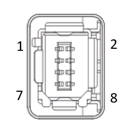
| Pin | Signal | Name | Function Description | |
| 1 | 0V | STO Reference Ground | When not connecting to safety devices, use to short-circuit SF1 and SF2. Do not use for external device power supply. | |
| 2 | 24V | STO Power Supply 24V | ||
| 3 | SF1- | STO control signal 1 negative input terminal | When the SF1 signal or SF2 signal is OFF, the STO safety function will be activated | |
| 4 | SF1+ | STO control signal 1 positive input terminal | ||
| 5 | SF2- | STO control signal 2 negative input terminal | ||
| 6 | SF2+ | STO control signal 2 positive input terminal | ||
| 7 | EDM- | Peripheral Device Monitoring Dual-End Differential Output | When the SF1 signal or SF2 signal is OFF, the EDM signal is set to ON | |
| 8 | EDM+ | |||
STO Wiring Diagram
