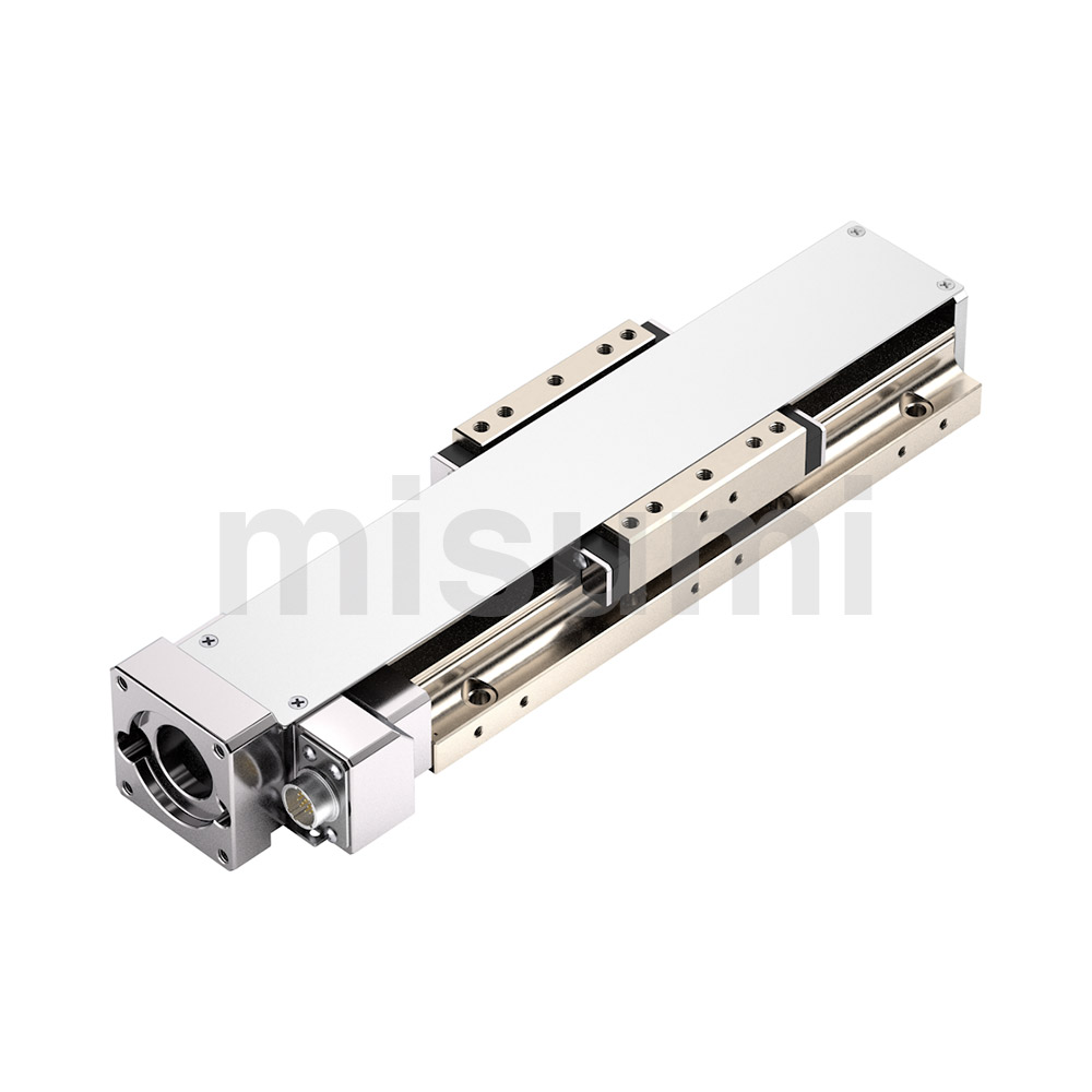
X-Axis Motorized Positioning Stages, Long stroke, Linear Ball Guide Type With Cover, Positioning Repeatability ±1μ
Caution
Product Description
The wiring diagram for November 2024 has been updated. Please refer to the website for confirmation.


E-XMBSXCH60□□-R-S3
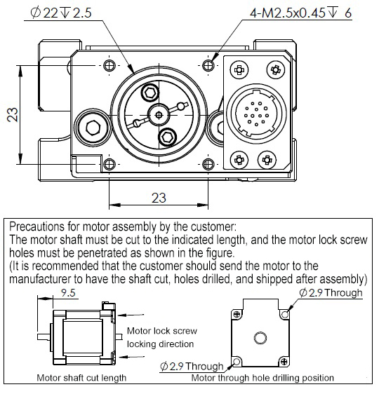
Note: 60100 to 60200: Compatible screws (included) M2.5 × 0.45 pitch x 55 mm length, quantity: 2 pcs.
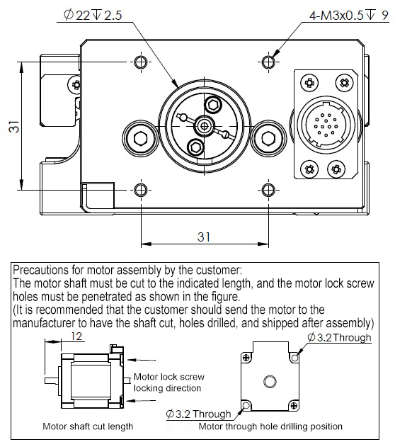
E-XMBSXCH80□□-R-S4
 Material: Steel
 Surface treatment: Chemical nickel plating
| Type | Slide Table Length (mm) |  Cover Plate Position |  Motor Motor |  Driver Driver |  Cable CableLength (m) | Mechanical Specifications | Accuracy Specifications | Sensor | ||||||||||||
 Type Type |  Type Type | Travel distance (mm) | Load capacity (N) | Weight (kg) | Resolution (pulses) | Maximum speed | Unidirectional positioning accuracy | Repeat positioning accuracy | Non-effective movement | Parallelism | Straightness | Motion parallelism | Limit sensor | Origin sensor (ORG1) | ||||||
| E-XMBSXCH | X axis | 6030 | 60 × 60 | R | Blank (with standard stepper motor) S1 (with servo bracket PCD=45) S2 (With servo bracket PCD=46) S3 (With 28-frame stepper motor mounting bracket) S4 (with 42-frame stepper motor mounting bracket) | A (single-axis pulse driver) N (No driver) E (EtherCat bus driver) | 2 (2-meter cable) 4 (4-meter cable) | 30 | 117.6 | 1.34 | 5 µm | 20 mm/sec | 15 µm | ±1 µm | 2 µm | 30 µm | 3 | 15 µm | Yes | Yes |
| 6050 | 50 | 1.44 | ||||||||||||||||||
| 6075 | 75 | 1.60 | ||||||||||||||||||
| 60100 | 100 | 1.86 | 10µm | 45 mm/sec | 5 | |||||||||||||||
| 60150 | 150 | 2.16 | 20µm | 25µm | ||||||||||||||||
| 60200 | 200 | 2.48 | 7 | |||||||||||||||||
| 8030 | 80 × 80 | 30 | 176.4 | 2.66 | 5 µm | 20 mm/sec | 15 µm | 3 | 15 µm | |||||||||||
| 8050 | 50 | 2.85 | 5 | |||||||||||||||||
| 8075 | 75 | 3.19 | ||||||||||||||||||
| 80100 | 100 | 3.36 | ||||||||||||||||||
 Driver: The pulse driver model used in this series is E-DR42C.Bus driver brand and model: Leadshine DM3C-EC522.Cable: The cable models used in this series are HRS12-2M (2-meter cable) / HRS12-4M (4-meter cable).Servo motor mounting bracket type. Recommended motor brands: Yaskawa, Inovance, Mitsubishi, Leadshine, Moons, etc. Recommended power: 50W, 100W. Please carefully check the motor mounting dimensions.Motor S3 is only applicable for model E-XMBSXCH60□□, motor S4 is only applicable for model E-XMBSXCH80□□.
■ General specifications
| E-XMBSXCH6030 | E-XMBSXCH6050 | E-XMBSXCH6075 | E-XMBSXCH60100 | E-XMBSXCH60150 | E-XMBSXCH60200 | ||
| Feed screw | Ball screw ⌀8, lead 1 mm | Ball screw ⌀8, lead 2 mm | |||||
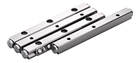
| Guide rail | Linear ball guide type | ||||||
| Motor | Type | 2-phase standard stepper motor 1.3 A/phase | 2-phase high torque stepper motor 1.3 A/phase | ||||
| Step angle | 1.8° | ||||||
| Pulse driver | Power supply voltage | 24 to 36 V DC | |||||
| Output current | 0.3 A to 2.2 A/phase (peak) | ||||||
| Pulse signal voltage | 5VDC | ||||||
| Pulse input mode | Pulse + direction or dual pulse | ||||||
| Microstep settings | 200 to 25600 | ||||||
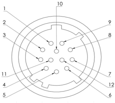
| Connector | Type | HR10A-10R-12P (Hirose) | |||||
| Receiver side type | HR10A-10P-12S (Hirose) | ||||||
| Sensor board | Power supply voltage | 24 V DC ±10% | |||||
| Sensor type | Miniature photo sensor RPI-0125 (ROHM) | ||||||
| Control output | NPN open collector output | ||||||
| Output logic | When detected (light blocked): output transistor OFF (not conducting) | ||||||
| E-XMBSXCH8030 | E-XMBSXCH8050 | E-XMBSXCH8075 | E-XMBSXCH80100 | |||
| Feed screw | Ball screw ⌀8, lead 1 mm | |||||
| Guide rail | Linear ball guide type | |||||
| Motor | Type | 2-phase standard stepper motor 2.0 A/phase | ||||
| Step angle | 1.8° | |||||
| Pulse driver | Power supply voltage | 24 to 36 V DC | ||||
| Output current | 0.3 A to 2.2 A/phase (peak) | |||||
| Pulse signal voltage | 5VDC | |||||
| Pulse input mode | Pulse + direction or dual pulse | |||||
| Microstep settings | 200 to 25600 | |||||
| Connector | Type | HR10A-10R-12P (Hirose) | ||||
| Receiver side type | HR10A-10P-12S (Hirose) | |||||
| Sensor board | Power supply voltage | 24 V DC ±10% | ||||
| Sensor type | Miniature photo sensor RPI-0125 (ROHM) | |||||
| Control output | NPN open collector output | |||||
| Output logic | When detected (light blocked): output transistor OFF (not conducting) | |||||
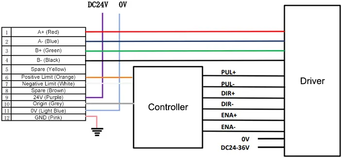
■ Connector pin arrangement
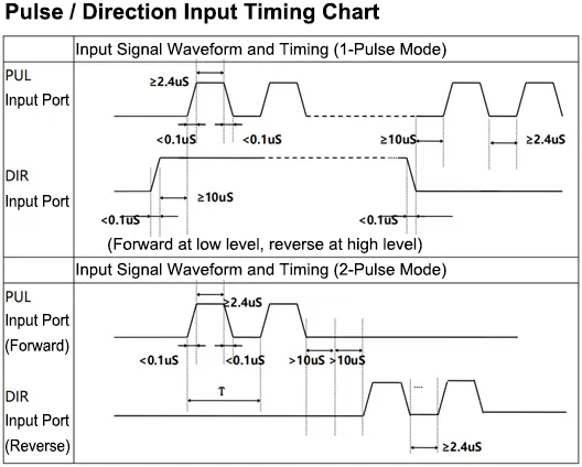
■ Timing diagram
Pulse driver
Feature 2: Localized production and optimized structure enable a low price.
Feature 3: Additional positioning holes on the slide table surface allow for quick assembly and disassembly.
Feature 4: The main body is made of steel with a chemical nickel plating, providing not only high rigidity but also excellent rust resistance.
■ Slide Table Operating Environment
Operating environment: 10 to 50°C, 20 to 70% RH (non-condensing)
Recommended environment: 22±5°C, 20 to 70% RH (non-condensing)
Please avoid using the slide table in the following environments
(1) Dusty environments (especially metal powder)
(2) Environments with direct sunlight or heat radiation
(3) Near fire sources
(4) Environments with corrosive or flammable gases
(5) Environments with splashing water or oil
(6) Environments with strong vibration or impact
(7) Environments with organic solvents or high salt content
■ Maintenance of the Slide Table
There is no unified regular maintenance standard due to differences in grease types and operating environments. Depending on the drive conditions and the type of guide rail, please be sure to check the grease at least once a month.
| Electronics/Home Appliances | Automotive | Medical | ||
 |  |  | ||
| Smartphones | Semiconductors | Lithium batteries | ||
 |  |  |
Compatible drivers support dual pulse and pulse + direction control. For installation dimensions and user manual, refer to: E-DR42C
■ Bus Driver
For installation dimensions and user manual of the driver, refer to Leadshine DM3C-EC522
| Direction of movement | ||||||
| X axis | Rotary axis | Goniometer | Z axis | Multi-axis combination | ||
| Guide mechanism | 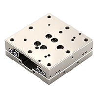 Linear ball | Thin type, repeatability ±1.5µ Standard type, repeatability ±1µ Standard type, repeatability ±1.5µ With recirculator, standard type, repeatability ±1.5µ/±2µ With recirculator, standard type, repeatability ±1µ With recirculator cover, standard type, repeatability ±1µ Repeatability ±5µ | — | — | Lifting type Repeatability ±5µ Repeatability ±5µ | Repeatability ±5µ |
 Crossed roller | Repeatability ±1.5µ Repeatability ±1µ | — | Repeatability ±0.006° Repeatability ±0.01° | Repeatability ±1µ | Repeatability ±0.01° | |
| Displacement mechanism | 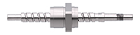 Ball screw | — | Repeat positioning accuracy ±0.005° Repeat positioning accuracy ±0.01° | — | — | — |
 Worm gear and worm | — | Repeatability ±0.05° Repeatability ±0.08° | — | — | — | |