Jaw Couplings Clamping Type

Brand :
MISUMI
Caution
Product Description
Jaw Couplings are an economy item, The price is cheaper than the MISUMI standard product.They offer a wide variety of sizes to choose from.
[Feature]
● Shaft Hole Diameter Minimum/Maximum (mm.): 4 and 80
● Outside Diameter Minimum/Maximum (mm.): 4 and 80
● Overall Length Minimum/Maximum (mm.) : 25 and 160
● Material :
Hub - Aluminum Alloy
Spacer - Polyurethane
[Application]
Jaw Couplings are commonly used in various applications in factory automation systems
Product Overview
Jaw couplings, also known as spider couplings, consist of two metal jaw hubs and one elastomer resin spider.
The res in spider helps absorb the impact of inertial loads during start and stop operations. Easy to assemble and disassemble.
Applicable motor types: Recommended for use with stepper motors and general-purpose motors.
The res in spider helps absorb the impact of inertial loads during start and stop operations. Easy to assemble and disassemble.
Applicable motor types: Recommended for use with stepper motors and general-purpose motors.
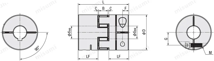
Dimensional Drawing
Keyway specifications require selecting additional machining parameters LK/RK
E-LMPJC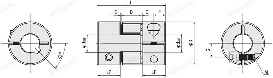
Outer diameter ⌀35–⌀40
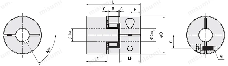
Outer diameter ⌀55-⌀120
 Be sure to use a torque wrench to tighten the bolts according to the specified tightening torque in the specification table to avoid thread stripping caused by excessive force. Keyway specifications require selecting additional machining parameters LK/RK
E-LMPJC
Outer diameter ⌀14–⌀30

Outer diameter ⌀35–⌀40

Outer diameter ⌀55-⌀120

 Be sure to use a torque wrench to tighten the bolts according to the specified tightening torque in the specification table to avoid thread stripping caused by excessive force. Keyway specifications require selecting additional machining parameters LK/RK
| TYPE | Adjusting ring material | Shore hardness A | Color |
| E-LMPJC | Polyurethane | 98 | Red |
| E-LMPJY | 90 | Yellow | |
| E-LMPJB | 80 | Blue |
Specification Overview
· Material Table
| Part |  Material Material |  Surface treatment Surface treatment |  Accessories Accessories |
| Hub | Aluminum alloy | Anodized finish | Hex socket bolt |
| Adjustment ring | Polyurethane | — |
Specification Table
Please follow the selection steps  to
to  , choose the type and parameters, and then place your order.
Please adjust the shaft insertion amount according to the "LF" dimensions in the catalog.
The red adjustment ring in the center of the standard product is solid.
■ Characteristics
Allowable torque varies with temperature.
Additional machining - keyway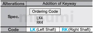
 to
to  , choose the type and parameters, and then place your order.
Type (Type· DL) DL) | — |  d1 d1 | — | d2 |
| E-LMPJC20L30 E-LMPJC30L35 | — — | 7 7 | — — | 8 9 |
Unit: mm
| Type | d1 and d2 selection (but d1 ≤ d2) | LF | B | C | F | Inner bore ⌀d | Locking bolt (M) | G | |||||||||||||||||
| Type | D | L | |||||||||||||||||||||||
| E-LMPJC (adjustment ring red) E-LMPJY (adjustment ring yellow) E-LMPJB (Adjustment ring blue) | 14 | L22 | 3 | 4 | 5 | 6 | 6.35 | 7.5 | 6.2 | 0.4 | 3.75 | ⌀3–⌀4 | 2.5 | 4 | |||||||||||
| ⌀5–⌀6.35 | 2 | 4.5 | |||||||||||||||||||||||
| 20 | L30 | 3 | 4 | 5 | 6 | 6.35 | 7 | 8 | 9 | 9.525 | 10 | 10.3 | 8 | 0.7 | 5.10 | ⌀3-⌀8 | 3 | 6.3 | |||||||
| ⌀9-⌀10 | 2.5 | 7 | |||||||||||||||||||||||
| 25 | L30 | 5 | 6 | 6.35 | 7 | 8 | 9 | 9.525 | 10 | 11 | 12 | 12.7 | 13 | 14 | 8.85 | 10.3 | 1 | 4.40 | ⌀5-⌀10 | 4 | 8 | ||||
| ⌀11-⌀14 | 3 | 9.5 | |||||||||||||||||||||||
| 25 | L34 | 5 | 6 | 6.35 | 7 | 8 | 9 | 9.525 | 10 | 11 | 12 | 12.7 | 13 | 14 | 10.85 | 10.3 | 1 | 5.40 | ⌀5-⌀10 | 4 | 8 | ||||
| ⌀11-⌀14 | 3 | 9.5 | |||||||||||||||||||||||
| 30 | L35 | 5 | 6 | 6.35 | 7 | 8 | 9 | 9.525 | 10 | 11 | 12 | 12.7 | 13 | 14 | 15 | 16 | 11.7 | 10 | 0.8 | 5.80 | ⌀5-⌀14 | 4 | 9.7 | ||
| ⌀15-⌀16 | 3 | 10.5 | |||||||||||||||||||||||
| 35 | L50 | 8 | 9 | 9.525 | 10 | 11 | 12 | 12.7 | 13 | 14 | 15 | 16 | 17 | 18 | 19 | 20 | 19.35 | 9.3 | 1 | 9.70 | ⌀8-⌀18 | 4 | 12 | ||
| ⌀19-⌀20 | 3 | 13 | |||||||||||||||||||||||
| 40 | L55 | 8 | 9 | 9.525 | 10 | 11 | 12 | 12.7 | 13 | 14 | 15 | 16 | 17 | 18 | 19 | 20 | 22 | 20.6 | 10.8 | 1.5 | 10.30 | ⌀8-19 | 5 | 13 | |
| ⌀20-⌀22 | 4 | 14.8 | |||||||||||||||||||||||
| 40 | L66 | 8 | 9 | 9.525 | 10 | 11 | 12 | 12.7 | 13 | 14 | 15 | 16 | 17 | 18 | 19 | 20 | 22 | 26.1 | 10.8 | 1.5 | 7.50 | ⌀8-19 | 5 | 13 | |
| ⌀20-⌀22 | 4 | 14.8 | |||||||||||||||||||||||
| 55 | L78 | 12 | 12.7 | 13 | 14 | 15 | 16 | 17 | 18 | 19 | 20 | 22 | 24 | 25 | 28 | 30 | 30.8 | 13.9 | 1.3 | 9.50 | ⌀12-⌀30 | 6 | 20 | ||
| 65 | L90 | 14 | 15 | 16 | 17 | 18 | 19 | 20 | 22 | 24 | 25 | 28 | 30 | 32 | 35 | 38 | 36 | 15 | 1.5 | 12 | ⌀14-⌀35 | 8 | 23.5 | ||
| ⌀38 | 6 | 25 | |||||||||||||||||||||||
| 80 | L114 | 19 | 20 | 22 | 24 | 25 | 28 | 30 | 32 | 35 | 38 | 40 | 42 | 45 | 45.75 | 18.5 | 2 | 15 | ⌀19-⌀45 | 8 | 29 | ||||
| 95 | L126 | 20 | 22 | 24 | 25 | 28 | 30 | 32 | 35 | 38 | 40 | 42 | 45 | 50 | 55 | 51.3 | 20.4 | 1.5 | 15.50 | ⌀20-⌀50 | 10 | 34 | |||
| ⌀55 | 10 | 35 | |||||||||||||||||||||||
| 105 | L140 | 20 | 22 | 24 | 25 | 28 | 30 | 32 | 35 | 38 | 40 | 42 | 45 | 50 | 55 | 60 | 57.3 | 20.4 | 2.5 | 17.50 | ⌀20-⌀60 | 10 | 38 | ||
Please adjust the shaft insertion amount according to the "LF" dimensions in the catalog.The red adjustment ring in the center of the standard product is solid.■ Characteristics
| Type | Rated torque (N⋅m) | Allowable angular misalignment (°) | Allowable eccentricity (mm) | Static torsional stiffness (N⋅m/rad) | Maximum speed (r/min) | Moment of inertia (kg·m2) | Allowable axial amplitude (mm) | Locking torque (N⋅m) | Weight g | ||||||||
| Type | D | L | E-LMPJC | E-LMPJY | E-LMPJB | E-LMPJC | E-LMPJY | E-LMPJB | E-LMPJC | E-LMPJY | E-LMPJB | ||||||
| E-LMPJC (adjustment ring red) E-LMPJY (adjustment ring yellow) E-LMPJB (Adjustment ring blue) | |||||||||||||||||
| 14 | L22 | 1.1 | 0.7 | 0.4 | 1 | 0.02 | 0.03 | 0.04 | 46 | 28 | 17 | 19000 | 2.0 × 10⁻⁷ | ±0.6 | 11 | 10 | |
| 20 | L30 | 2.8 | 1.7 | 1 | 1 | 0.02 | 0.03 | 0.04 | 55 | 33 | 20 | 17000 | 1.1 × 10⁻⁶ | ±0.6 | 3.5 | 19 | |
| 25 | L30 | 6 | 3.6 | 2.1 | 1 | 0.02 | 0.03 | 0.04 | 65 | 39 | 24 | 16000 | 5.2 × 10⁻⁶ | ±0.6 | 3.5 | 33 | |
| 25 | L34 | 1 | 0.02 | 0.03 | 0.04 | 65 | 39 | 24 | 16000 | 5.2 × 10⁻⁶ | ±0.6 | 3.5 | 42 | ||||
| 30 | L35 | 6.5 | 3.9 | 2.3 | 1 | 0.02 | 0.03 | 0.04 | 72 | 43 | 26 | 12000 | 6.2 × 10⁻⁶ | ±0.6 | 3.5 | 50 | |
| 35 | L50 | 15 | 9 | 5.3 | 1 | 0.02 | 0.03 | 0.04 | 200 | 120 | 72 | 10000 | 8.1 × 10⁻⁶ | ±0.6 | 8 | 45 | |
| 40 | L55 | 32 | 19 | 11 | 1 | 0.02 | 0.03 | 0.04 | 500 | 300 | 180 | 10000 | 3.8 × 10⁻⁵ | ±0.8 | 8 | 127 | |
| 40 | L66 | 1 | 0.02 | 0.03 | 0.04 | 550 | 330 | 198 | 10000 | 3.9 × 10⁻⁵ | ±0.8 | 154 | |||||
| 55 | L78 | 46 | 28 | 16 | 1 | 0.02 | 0.03 | 0.04 | 1500 | 900 | 540 | 8000 | 1.6 × 10⁻³ | ±0.8 | 13 | 341 | |
| 65 | L90 | 109 | 66 | 38 | 1 | 0.02 | 0.03 | 0.04 | 2800 | 1680 | 1008 | 6000 | 2.5 × 10⁻³ | ±0.8 | 28 | 583 | |
| 80 | L114 | 135 | 81 | 47 | 1 | 0.02 | 0.03 | 0.04 | 3500 | 2100 | 1260 | 4600 | 2.8 × 10⁻³ | ±1.0 | 28 | 1000 | |
| 95 | L126 | 250 | 150 | 88 | 1 | 0.02 | 0.03 | 0.04 | 5000 | 3000 | 1800 | 3800 | 3.0 × 10⁻³ | ±1.0 | 40 | 1500 | |
| 105 | L140 | 420 | 252 | 147 | 1 | 0.02 | 0.03 | 0.04 | 5400 | 3240 | 1944 | 3400 | 3.2 × 10⁻³ | ±1.0 | 75 | 2000 | |
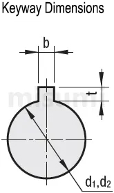
Allowable torque varies with temperature.Additional machining - keyway


| Shaft bore diameterd1·d2 | b (Keyway width) | t Keyway depth | Key nominal size b × h | |
| LK | RK | |||
| 6 to 8 | 2 | 2 | 1 | 2 × 2 |
| 8 to 10 | 3 | 3 | 1.4 | 3 × 3 |
| 11 to 12 | 4 | 4 | 1.8 | 4 × 4 |
| 12.7 to 17 | 5 | 5 | 2.3 | 5 × 5 |
| 18 to 22 | 6 | 6 | 2.8 | 6 × 6 |
| 23 to 30 | 8 | 8 | 3.3 | 8 × 7 |
| 31 to 38 | 10 | 10 | 3.3 | 10 × 8 |
| 39 to 44 | 12 | 12 | 3.3 | 12 × 8 |
| 45 to 50 | 14 | 14 | 3.8 | 14 × 9 |
| 51 to 58 | 16 | 16 | 4.3 | 16 × 10 |
| 59 to 65 | 18 | 18 | 4.4 | 18 × 11 |
| 66 to 75 | 20 | 20 | 4.9 | 20 × 12 |
| 76 to 85 | 22 | 22 | 5.4 | 22 × 14 |
| 86 to 95 | 25 | 25 | 5.4 | 25 × 14 |
Product Features
The features of jaw couplings are as follows:
Simple structure, no lubrication required, easy maintenance, convenient inspection, maintenance-free, and capable of continuous long-term operation.
Polyurethane elastomer components are wear-resistant and oil-resistant, have high load capacity, long service life, and are safe and reliable.
Provides excellent vibration damping, cushioning, and electrical insulation performance. Offers large axial, radial, and angular compensation capabilities.
Simple structure, small radial dimensions, lightweight, low moment of inertia, suitable for medium and high-speed applications.
Usage Method
■ Installation method
STEP1 Insert the coupling
Make sure the clamping bolts are loosened, then remove any dust, foreign matter, or oil from the shaft and the coupling bore.
Next, when inserting the coupling onto the shaft, be careful not to subject the diaphragm to excessive stress such as compression or tension.
STEP2 Adjustment using a jig
Please use a jig to precisely adjust and secure the concentricity of the left and right hubs of the coupling.
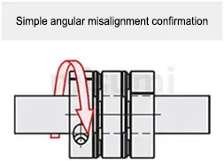
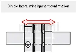
STEP3 Simple eccentricity and angular misalignment check
With the bolts loosened, slide the coupling axially to confirm smooth operation.
Next, rotate the coupling and make sure it operates smoothly.
Eccentricity is not allowed for single-disc couplings, so please position them accurately.
STEP4 Installation
Adjust the shaft insertion amount according to the ℓ dimension in the product catalog, and use a torque wrench to tighten to the specified torque.
*If the specified torque cannot be reached in one tightening, please tighten the left and right clamps in a crisscross pattern over 2 or 3 rounds.
STEP1 Insert the coupling
Make sure the clamping bolts are loosened, then remove any dust, foreign matter, or oil from the shaft and the coupling bore.
Next, when inserting the coupling onto the shaft, be careful not to subject the diaphragm to excessive stress such as compression or tension.
STEP2 Adjustment using a jig
Please use a jig to precisely adjust and secure the concentricity of the left and right hubs of the coupling.
STEP3 Simple eccentricity and angular misalignment check
With the bolts loosened, slide the coupling axially to confirm smooth operation.
Next, rotate the coupling and make sure it operates smoothly.
Eccentricity is not allowed for single-disc couplings, so please position them accurately.


STEP4 Installation
Adjust the shaft insertion amount according to the ℓ dimension in the product catalog, and use a torque wrench to tighten to the specified torque.
*If the specified torque cannot be reached in one tightening, please tighten the left and right clamps in a crisscross pattern over 2 or 3 rounds.
Precautions
■ Alignment Adjustment
1. Couplings allow for shaft misalignment, transmission of rotational angle, and torque, but if the shaft misalignment exceeds the allowable value, vibration may occur or the service life may be drastically reduced. Be sure to perform alignment adjustment.
2. Shaft misalignment includes eccentricity (parallel error between two shaft centers), angular misalignment (angular error between two shaft centers), and axial displacement (axial movement of the shaft).
Please calibrate and adjust the shafts to ensure that the shaft misalignment is within the allowable values specified in the dimensions and performance tables of each product.
3. The allowable values for shaft misalignment listed in the dimensions and performance tables refer to the case where only one of eccentricity, angular misalignment, or axial displacement occurs individually. When two or more types of shaft misalignment occur simultaneously, the corresponding allowable values should each be halved.
4. Shaft misalignment does not only occur during assembly to the equipment; vibration during operation, thermal expansion, and bearing wear are also major causes. Therefore, it is recommended to set the shaft misalignment to less than one-third of the allowable value.
Example of Use
 Coupling Example of Use 1: Motor × Gearbox |  Coupling Example of Use 2: Motor × Ball Screw |
 Coupling Example of Use 3: Motor × Encoder |  Coupling Example of Use 4: Motor × Testing Machine |
Related Products
| Economy Coupling Jaw Type Set Screw Type | Economy Coupling Jaw Type Carbon Steel Clamp Type | Economy Coupling Jaw Type Carbon Steel Set Screw Type | ||
 |  |  |