(!) Since support from Microsoft will end on January 14 2020, Windows 7 user might not be able to use MISUMI website effectively. Please consider to update your system as ‘MISUMI Website system requirement’.


-
Viewed
Products -
My
Components - Cart
- แจ้งวันหยุดทำการในเดือน กรกฎาคมและสิงหาคม 2567 | Notice holiday in July and August 2024 > คลิก
-
 My Components
-
 Similar Products
 Product Detail
- CAD Data unavailable
Specification/Dimensions
-
Shaft Bore Dia.1 d1 (or d)(Ø)
-
Shaft Bore Dia. 2 d2 (or d)(Ø)
-
O.D.(Ø)
-
Overall Length(mm)
-
type
- E-LMPJC
Days to Ship
-
- All
- 9 Day(s) or Less
- 10 Day(s) or Less
- 15 Day(s) or Less
- 18 Day(s) or Less
Specify Alterations
Jaw Couplings Clamping Type

Copy Part Number URL to Clipboard
The part number URL has been copied into your clipboard.-
- Price :
- ---
-
- Qty :
-
-
- Days to Ship :
- ---
-
- Total Price :
- ---
Select part number to Order Now/ Add to Cart
- CAD Data unavailable
Product Description
Jaw Couplings are an economy item, The price is cheaper than the MISUMI standard product.They offer a wide variety of sizes to choose from.
[Feature]
● Shaft Hole Diameter Minimum/Maximum (mm.): 4 and 80
● Outside Diameter Minimum/Maximum (mm.): 4 and 80
● Overall Length Minimum/Maximum (mm.) : 25 and 160
● Material :
Hub - Aluminum Alloy
Spacer - Polyurethane
[Application]
Jaw Couplings are commonly used in various applications in factory automation systems
Product Overview of Flexible Shaft Couplings
・The resin adjustment ring can alleviate the inertial load impact during start and stop.
・Flexible Shaft Couplings is Easy to disassemble and assemble.
・Recommended for stepper motors and general-purpose motors.
Dimensional Drawing of Flexible Shaft Couplings

| Parts |  Material of Flexible Shaft Couplings Material of Flexible Shaft Couplings |  Surface Treatment Surface Treatment |  Accessory Accessory |
| Hub | Aluminum Alloy | Clear Anodized | Clamp Screw |
| Spacer | Polyurethane | - |
Specification Table of Flexible Shaft Couplings
 ~
~ to select the part no.
Part No.(Type of Flexible Shaft Couplings· DL) DL) | - |  d1 d1 | - | d2 |
| E-LMPJC20L25 E-LMPJC20L30 E-LMPJC30L35 | - - - | 5 7 7 | - - - | 6 8 9 |
| Part No. | d1、d2 Shaft Hole dia (d1≤d2) | LF | LP | F | |||||||||||||||||||||||||||||||||
 Type of Flexible Shaft Couplings Type of Flexible Shaft Couplings |  D D | L | |||||||||||||||||||||||||||||||||||
| E-LMPJC | 20 | L25 | 4 | 5 | 6 | 6.35 | 7 | 8 | 9 | 9.525 | 10 | 16.6 | 8.6 | 4.0 | |||||||||||||||||||||||
| 20 | L30 | 4 | 5 | 6 | 6.35 | 7 | 8 | 9 | 9.525 | 10 | 19.1 | 8.6 | 5.3 | ||||||||||||||||||||||||
| 25 | L30 | 5 | 6 | 6.35 | 7 | 8 | 9 | 9.525 | 10 | 11 | 12 | 12.7 | 13 | 14 | 20.5 | 11.6 | 5.6 | ||||||||||||||||||||
| 25 | L34 | 5 | 6 | 6.35 | 7 | 8 | 9 | 9.525 | 10 | 11 | 12 | 12.7 | 13 | 14 | 22.5 | 11.6 | 5.6 | ||||||||||||||||||||
| 30 | L35 | 5 | 6 | 6.35 | 7 | 8 | 9 | 9.525 | 10 | 11 | 12 | 12.7 | 13 | 14 | 15 | 16 | 22.5 | 10.9 | 5.75 | ||||||||||||||||||
| 30 | L40 | 5 | 6 | 6.35 | 7 | 8 | 9 | 9.525 | 10 | 11 | 12 | 12.7 | 13 | 14 | 15 | 16 | 25 | 10.9 | 7 | ||||||||||||||||||
| 35 | L50 | 8 | 9 | 9.525 | 10 | 11 | 12 | 12.7 | 13 | 14 | 15 | 16 | 17 | 18 | 19 | 20 | 30 | 11.5 | 10 | ||||||||||||||||||
| 40 | L40 | 8 | 9 | 9.525 | 10 | 11 | 12 | 12.7 | 13 | 14 | 15 | 16 | 17 | 18 | 19 | 20 | |||||||||||||||||||||
| 40 | L50 | 8 | 9 | 9.525 | 10 | 11 | 12 | 12.7 | 13 | 14 | 15 | 16 | 17 | 18 | 19 | 20 | 22 | 31.1 | 13.7 | 10 | |||||||||||||||||
| 40 | L55 | 8 | 9 | 9.525 | 10 | 11 | 12 | 12.7 | 13 | 14 | 15 | 16 | 17 | 18 | 19 | 20 | 22 | 33.6 | 13.7 | 10 | |||||||||||||||||
| 40 | L66 | 8 | 9 | 9.525 | 10 | 11 | 12 | 12.7 | 13 | 14 | 15 | 16 | 17 | 18 | 19 | 20 | 22 | 39.1 | 13.7 | 12.75 | |||||||||||||||||
| 55 | L78 | 12 | 12.7 | 13 | 14 | 15 | 16 | 17 | 18 | 19 | 20 | 22 | 24 | 25 | 28 | 30 | 46.2 | 16.1 | 15.5 | ||||||||||||||||||
| 65 | L90 | 14 | 15 | 16 | 17 | 18 | 19 | 20 | 22 | 24 | 25 | 28 | 30 | 32 | 35 | 38 | 52.9 | 16.7 | 18.1 | ||||||||||||||||||
| 80 | L114 | 19 | 20 | 22 | 24 | 25 | 28 | 30 | 32 | 35 | 38 | 40 | 42 | 45 | 67 | 22.5 | 15.5 | ||||||||||||||||||||
| 95 | L126 | 20 | 22 | 24 | 25 | 28 | 30 | 32 | 35 | 38 | 40 | 42 | 45 | 50 | 55 | 74.5 | 24.0 | 20.0 | |||||||||||||||||||
| 105 | L140 | 20 | 22 | 24 | 25 | 28 | 30 | 32 | 35 | 38 | 40 | 42 | 45 | 50 | 55 | 60 | 83.2 | 26.4 | 20.0 | ||||||||||||||||||
| 120 | L160 | 25 | 28 | 30 | 32 | 35 | 38 | 40 | 42 | 45 | 50 | 55 | 60 | 65 | 70 | 75 | 80 | 93.7 | 27.4 | 25.0 | |||||||||||||||||
■Characteristic Values of Flexible Shaft Couplings
| Part No. of Flexible Shaft Couplings | Rated Torque (N·m) | Angular Misalignment ( ° ) | Lateral Misalignment (mm) | Static Torsional Spring Constant (N·m/rad) | Max. Rotational Speed (r/min) | Moment of Inertia (kg·m2) | Allowable Axial Misalignment (mm) | Clamp Screw | Mass g | |||
| Type of Flexible Shaft Couplings | D | L | M | Tightening Torque (N.m) | ||||||||
| E-LMPJC | ||||||||||||
| 20 | L25 | 2.8 | 1 | 0.02 | 55 | 17000 | 1.0x10⁻⁶ | ±0.6 | M3 | 1.5 | 15 | |
| 20 | L30 | 1 | 0.02 | 55 | 17000 | 1.1x10⁻⁶ | ±0.6 | M4 | 3.5 | 19 | ||
| 25 | L30 | 6 | 1 | 0.02 | 65 | 16000 | 5.2x10⁻⁶ | ±0.6 | M4 | 3.5 | 33 | |
| 25 | L34 | 1 | 0.02 | 65 | 16000 | 5.2x10⁻⁶ | ±0.6 | M4 | 3.5 | 42 | ||
| 30 | L35 | 6.5 | 1 | 0.02 | 72 | 12000 | 6.2x10⁻⁶ | ±0.6 | M4 | 3.5 | 50 | |
| 30 | L40 | 1 | 0.02 | 72 | 12000 | 6.2x10⁻⁶ | ±0.6 | M4 | 8 | 60 | ||
| 35 | L50 | 15 | 1 | 0.02 | 200 | 10000 | 8.1x10⁻⁶ | ±0.6 | M5 | 8 | 45 | |
| 40 | L40 | 32 | 1 | 0.02 | 450 | 10000 | 3.8x10⁻⁵ | ±0.8 | 115 | |||
| 40 | L50 | 1 | 0.02 | 450 | 10000 | 3.8x10⁻⁵ | ±0.8 | 115 | ||||
| 40 | L55 | 1 | 0.02 | 500 | 10000 | 3.8x10⁻⁵ | ±0.8 | 127 | ||||
| 40 | L66 | 1 | 0.02 | 550 | 10000 | 3.9x10⁻⁵ | ±0.8 | 154 | ||||
| 55 | L78 | 46 | 1 | 0.02 | 1500 | 8000 | 1.6x10⁻³ | ±0.8 | M6 | 13 | 341 | |
| 65 | L90 | 109 | 1 | 0.02 | 2800 | 6000 | 3.8x10⁻³ | ±0.8 | M8 | 28 | 583 | |
| 80 | L114 | 135 | 1 | 0.02 | 3500 | 4600 | 1.8x10⁻³ | ±1.0 | M8 | 28 | 1000 | |
| 95 | L126 | 250 | 1 | 0.02 | 5000 | 3800 | 1.8x10⁻³ | ±1.0 | M10 | 40 | 1500 | |
| 105 | L140 | 420 | 1 | 0.02 | 5400 | 3400 | 3.1x10⁻³ | ±1.0 | M12 | 75 | 2000 | |
| 120 | L160 | 520 | 1 | 0.02 | 6500 | 3000 | 4.3x10⁻³ | ±1.0 | M12 | 75 | 2500 | |
 The Flexible Shaft Couplings allowable torque varies with temperature.Press the adjustment ring into the body to assemble.Press Spacer to the body when install.
| Shaft Bore Dia. d1·d2 | b(Keyway Width) | t Keyway Depth | Keyway Nominal Dim. b X h | |
| LK | RK | |||
| 8~10 | 3 | 3 | 1.4 | 3x3 |
| 11~12 | 4 | 4 | 1.8 | 4x4 |
| 13~17 | 5 | 5 | 2.3 | 5x5 |
| 18~22 | 6 | 6 | 2.8 | 6x6 |
| 23~30 | 8 | 8 | 3.3 | 8x7 |
| 31~38 | 10 | 10 | 3.3 | 10x8 |
| 39~44 | 12 | 12 | 3.3 | 12x8 |
| 45~50 | 14 | 14 | 3.8 | 14x9 |
| 51~58 | 16 | 16 | 4.3 | 16x10 |
| 59~65 | 18 | 18 | 4.4 | 18x11 |
| 66~75 | 20 | 20 | 4.9 | 20x12 |
| 76~85 | 22 | 22 | 5.4 | 22x14 |
| 86~95 | 25 | 25 | 5.4 | 25x14 |
Product Features of Flexible Shaft Couplings
It has a simple structure, no lubrication required / easy to repair and inspect / maintenance-free. It can operated continuously for a long time.
Polyurethane elastic parts are wear-resistant and oil-resistant, have large load capacity, long service life, and are Flexible Shaft Couplings is safe and reliable.
This product is suitable for medium and high-speed applications.
Usage Method of Flexible Shaft Couplings
STEP1 Insert the coupling
Confirm that the clamping bolt has been unscrewed, and then remove the dust, foreign matter and oil from the shaft and Flexible Shaft Couplings bore.
Then, when inserting the coupling into the shaft, please be careful not to put the disc under excessive stress such as compression or tension.
STEP2 Use fixture to adjust
Please use fixture to adjust and fix the concentricity of the left and right hubs of the Flexible Shaft Couplings with high accuracy.
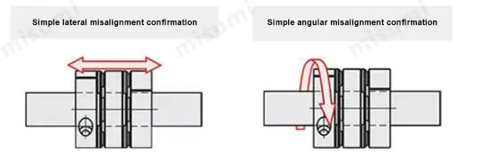
STEP3 Simple lateral misalignment and angular misalignment confirmation
Under the condition of unscrewed bolts, make the Flexible Shaft Couplings slide axially and confirm its smooth movement.
Then, rotate the coupling to make sure it moves smoothly.
Lateral misalignment is not allowed for single disc type coupling, so carry out positioning securely.
Please adjust the shaft insertion amount according to the dimension ℓ in the product catalog, and use a torque wrench to tighten with the specified torque.
* If the specified torque cannot be reached once, please cross fasten the left and right clamps twice or three times.
Example Use of Flexible Shaft Couplings
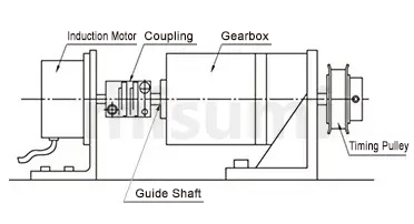
Use example of Flexible Shaft Couplings 1: motor × gear box
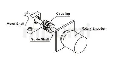
Use example of Flexible Shaft Couplings 3: motor × encoder
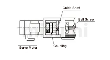
Use example of Flexible Shaft Couplings 2: motor × ball screw
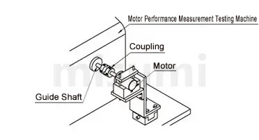
Use example of Flexible Shaft Couplings 4: motor × measuring tester
Precautions of Flexible Shaft Couplings
1. The Flexible Shaft Couplings allows axis deviation, and transmits rotation angle and torque, but when the axis deviation exceeds the allowable value, vibration will occur or the service life will be drastically reduced. Be sure to make calibration andadjustment.
2. Axis deviation includes lateral misalignment (parallel error of two axes), angular misalignment (angular error of two axes) and axial amplitude (axial movement of shaft).
Please calibrate and adjust the shaft to ensure that the axis deviation is below the allowable value recorded in the dimension and performance table of each product.
3. The allowable value of axis deviation recorded in the dimension and performance table refers to the situation when either lateral misalignment, angular misalignment or axial amplitude occurs alone. When more than two axis deviationsoccur at the same time, the corresponding allowable values are halved respectively.
4. Axis deviation not only occurs when assembling to the device, but also is caused by vibration, thermal expansion and bearing wear in operation. Therefore, it is recommended to set the axis deviation below 1/3 of the allowable value.
| Part Number |
|---|
| E-LMPJC20L25-[4,5,6,6.35,7,8,9,9.525,10]-[4,5,6,6.35,7,8,9,9.525,10] |
| E-LMPJC20L30-[4,5,6,6.35,7,8,9,9.525,10]-[4,5,6,6.35,7,8,9,9.525,10] |
| E-LMPJC25L30-[5,6,6.35,7,8,9,9.525,10,11,12,12.7,13,14]-[5,6,6.35,7,8,9,9.525,10,11,12,12.7,13,14] |
| E-LMPJC25L34-[5,6,6.35,7,8,9,9.525,10,11,12,12.7,13,14]-[5,6,6.35,7,8,9,9.525,10,11,12,12.7,13,14] |
| E-LMPJC30L35-[5,6,6.35,7,8,9,9.525,10,11,12,12.7,13,14,15,16]-[5,6,6.35,7,8,9,9.525,10,11,12,12.7,13,14,15,16] |
| E-LMPJC30L40-[5,6,6.35,7,8,9,9.525,10,11,12,12.7,13,14,15,16]-[5,6,6.35,7,8,9,9.525,10,11,12,12.7,13,14,15,16] |
| E-LMPJC35L50-[8,9,9.525,10,11,12,12.7,13,14,15,16,17,18,19,20]-[8,9,9.525,10,11,12,12.7,13,14,15,16,17,18,19,20] |
| E-LMPJC40L40-[8,9,9.525,10,11,12,12.7,13,14,15,16,17,18,19,20,22]-[8,9,9.525,10,11,12,12.7,13,14,15,16,17,18,19,20,22] |
| E-LMPJC40L50-[7,8,9,9.525,10,11,12,12.7,13,14,15,16,17,18,19,20,22]-[7,8,9,9.525,10,11,12,12.7,13,14,15,16,17,18,19,20,22] |
| E-LMPJC40L55-[7,8,9,9.525,10,11,12,12.7,13,14,15,16,17,18,19,20,22]-[7,8,9,9.525,10,11,12,12.7,13,14,15,16,17,18,19,20,22] |
| E-LMPJC40L66-[7,8,9,9.525,10,11,12,12.7,13,14,15,16,17,18,19,20,22]-[7,8,9,9.525,10,11,12,12.7,13,14,15,16,17,18,19,20,22] |
| E-LMPJC55L78-[12,12.7,13,14,15,16,17,18,19,20,22,24,25,28,30]-[12,12.7,13,14,15,16,17,18,19,20,22,24,25,28,30] |
| E-LMPJC65L90-[14,15,16,17,18,19,20,22,24,25,28,30,32,35,38]-[14,15,16,17,18,19,20,22,24,25,28,30,32,35,38] |
| E-LMPJC80L114-[19,20,22,24,25,28,30,32,35,38,40,42,45]-[19,20,22,24,25,28,30,32,35,38,40,42,45] |
| E-LMPJC95L126-[20,22,24,25,28,30,32,35,38,40,42,45,50,55]-[20,22,24,25,28,30,32,35,38,40,42,45,50,55] |
| E-LMPJC105L140-[20,22,24,25,28,30,32,35,38,40,42,45,50,55,60]-[20,22,24,25,28,30,32,35,38,40,42,45,50,55,60] |
| E-LMPJC120L160-[25,28,30,32,35,38,40,42,45,50,55,60,65,70,75,80]-[25,28,30,32,35,38,40,42,45,50,55,60,65,70,75,80] |
| Part Number | Price | Name | Minimum Order Qty. | Volume Discount | Days to Ship | RoHS | Shaft Bore Dia.1 d1 (or d) (Ø) | Shaft Bore Dia. 2 d2 (or d) (Ø) | O.D. (Ø) | Overall Length (mm) |
|---|---|---|---|---|---|---|---|---|---|---|
- | ECONOMY EL JAW COUPLING | 1 Piece(s) | 9 Day(s) | 10 | 4 ~ 10 | 4 ~ 10 | 20 | 25 | ||
- | ECONOMY EL JAW COUPLING | 1 Piece(s) | 10 Day(s) | 10 | 4 ~ 10 | 4 ~ 10 | 20 | 30 | ||
- | ECONOMY EL JAW COUPLING | 1 Piece(s) | 15 Day(s) | 10 | 5 ~ 14 | 5 ~ 14 | 25 | 30 | ||
- | ECONOMY EL JAW COUPLING | 1 Piece(s) | 15 Day(s) | 10 | 5 ~ 14 | 5 ~ 14 | 25 | 34 | ||
- | ECONOMY EL JAW COUPLING | 1 Piece(s) | 15 Day(s) | 10 | 5 ~ 16 | 5 ~ 16 | 30 | 35 | ||
- | ECONOMY EL JAW COUPLING | 1 Piece(s) | 15 Day(s) | 10 | 5 ~ 16 | 5 ~ 16 | 30 | 40 | ||
- | ECONOMY EL JAW COUPLING | 1 Piece(s) | 15 Day(s) | 10 | 8 ~ 20 | 8 ~ 20 | 35 | 50 | ||
- | ECONOMY EL JAW COUPLING | 1 Piece(s) | 15 Day(s) | 10 | 8 ~ 22 | 8 ~ 22 | 40 | 40 | ||
- | ECONOMY EL JAW COUPLING | 1 Piece(s) | 15 Day(s) | 10 | 7 ~ 22 | 7 ~ 22 | 40 | 50 | ||
- | ECONOMY EL JAW COUPLING | 1 Piece(s) | 10 Day(s) | 10 | 7 ~ 22 | 7 ~ 22 | 40 | 55 | ||
- | ECONOMY EL JAW COUPLING | 1 Piece(s) | 10 Day(s) | 10 | 7 ~ 22 | 7 ~ 22 | 40 | 66 | ||
- | ECONOMY EL JAW COUPLING | 1 Piece(s) | 18 Day(s) | 10 | 12 ~ 30 | 12 ~ 30 | 55 | 78 | ||
- | ECONOMY EL JAW COUPLING | 1 Piece(s) | 15 Day(s) | 10 | 14 ~ 38 | 14 ~ 38 | 65 | 90 | ||
- | ECONOMY EL JAW COUPLING | 1 Piece(s) | 10 Day(s) | 10 | 19 ~ 45 | 19 ~ 45 | 80 | 114 | ||
- | ECONOMY EL JAW COUPLING | 1 Piece(s) | 15 Day(s) | 10 | 20 ~ 55 | 20 ~ 55 | 95 | 126 | ||
- | ECONOMY EL JAW COUPLING | 1 Piece(s) | 15 Day(s) | 10 | 20 ~ 60 | 20 ~ 60 | 105 | 140 | ||
- | ECONOMY EL JAW COUPLING | 1 Piece(s) | 9 Day(s) | 10 | 25 ~ 80 | 25 ~ 80 | 120 | 160 |
Loading...
Basic Information
| Series Name | Jaw | Application | Standard / For Servo Motors / Stepping Motor | Features | High Torque Type / Low Moment of Inertia / Vibration Insulation |
|---|---|---|---|---|---|
| Allowable Misalignment | Angular Misalignment / Eccentricity / Axial Misalignment | Body Material | Aluminum Alloy | Product Category | Coupling Main Body |
| Buffer Material | Polyurethane | Operating Temperature(°C) | -20::60 | Shaft Tightening Method | Fastening Bolt |
| Shaft Hole Shape | Standard |
- The specifications and dimensions of some parts may not be fully covered. For exact details, refer to manufacturer catalogs .
Frequently Asked Questions (FAQ)
- Question: What are the characteristics of claw couplings?
- Answer: Claw couplings can absorb vibration, compensate radial and angular deviation, and are maintenance free, oil resistant and electrically insulated.
- Question: What are the applications of claw couplings?
- Answer: Applicable motor types for claw couplings: recommended for stepping motors and universal motors.
- Question: How to select according to the purpose, environment, working conditions?
- Answer: Please refer to the link page for specific instructions. https://www.misumi.com.cn/special/coupling/select/situation/
- Question: What is a coupling?
- Answer: A coupling is a part that connects two different rotating bodies (motor shaft, ball screw, etc.) and aims at transmitting torque. The load of assembly adjustment is reduced by absorbing the axis deviation (lateral misalignment, angular misalignment and axial amplitude) between rotating bodies. And in case of accidental overload, the coupling is destroyed and the rotating bodies are disconnected to protect the expensive power part and the whole device.
Payment Methods
- Credit Card
-
- Bank
-
- Prompt Pay
-


Social Media
MISUMI Contact
Copyright © MISUMI Corporation All Rights Reserved.
How can we improve?
How can we improve?