Rolled Ball Screws - Shaft Dia. 4; Lead 1 / 2 - Accuracy Grade C7
Brand :
MISUMI
Caution
- Download Free! >>Economy Series Catalog ver2023 (TH-EN)_Part01 CLICK here
Product Description
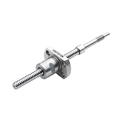
Rolled Ball Screws are an economy item, The price is cheaper than the MISUMI standard product.They offer a wide variety of sizes to choose from.
[Feature]
● Lead(mm) : 1 and 2
● Screw Diameter (mm) : 4
● Shaft Screw Overall Length L (mm.): 55 to 130, incrementing by 1 mm.
● Accuracy grade : C7
● Material :
Screw Shaft - S55C equivalent
Nut - SCM415H equivalent
[Application]
Rolled Ball Screws are commonly used in various applications in factory automation systems
Product Overview of Ball Screw
1. This series of products is the C7 Rolled Ball Screw with the shaft diameter of 4 and lead of 1/2.2. It is more suitable for feeding mechanisms in FA automation equipment.
3. The Ball Screw end is machined according to standard specifications. If the shaft end requires alteration, it should be specified according to the catalog.
Dimensional Drawing of Ball Screw
| Accuracy grade | Ball Screw Dia. | Lead | Ball Screw Shaft | Nut | ||||
 Material of Ball Screw Material of Ball Screw |  Hardness Hardness |  Surface Treatment Surface Treatment | Material of Ball Screw | Hardness | Surface Treatment | |||
| C7 | 4 | 1·2 | S55C equivalent | Induction hardening 58~62HRC | - | SCM415H equivalent | Carburized 58~62HRC | - |

*Accessory collar (1 pcs.)
Material of Ball Screw: SUS304
*Accessory collar (1 pcs.)
Material of Ball Screw: SUS304Specification Table of Ball Screw

| Part Number of Ball Screw |  L L(1mm increments) | Y | Number of Circuits | Basic Load Rating | Axial Play | Twisting Direction | |||
 Type of Ball Screw Type of Ball Screw |  Ball Screw Shaft O.D. Ball Screw Shaft O.D. |  Lead Lead | C (Dynamic) kN | C (Static) kN | |||||
| E-TBS | 04 | 01 | 55~130 | L-27 | 3 turns | 0.42 | 0.57 | 0.02 or Less | Right |
| 02 | 2.7 turns | ||||||||
Alterations of Ball Screw
| Part Number (Type·Ball Screw O.D.·Lead) | - | L | - | (RLC·SZC…etc.) | ||
| E-TBS0401 | - | 80 | - | RLC |
■Support side of Ball Screw
 When ⑤ and ⑥ are specified simultaneously, no male thread will be machined regardless of the value specified for U in ⑤.
When specifying any alteration, the nut motion range (Y dimension) may become shorter. Please make sure that the nut motion range is greater than the full length ofthe Ball Screw.
| Alterations of Ball Screw | Code of Ball Screw | Spec of Ball Screw. | ||||||||
①Ball Screw Orientation Reversed | RLC | Changes the Ball Screw direction. Ordering CodeRLC | ||||||||
②Machining on Support Side Ball Screw End | TFC | Machining added on the support side Ball Screw end. Ordering Code TFC
|
 When ⑤ and ⑥ are specified simultaneously, no male thread will be machined regardless of the value specified for U in ⑤.When specifying any alteration, the nut motion range (Y dimension) may become shorter. Please make sure that the nut motion range is greater than the full length ofthe Ball Screw.
■Fixed side
| Alterations of Ball Screw | Code of Ball Screw | Spec of Ball Screw. |
③Wrench Flats on Fixed Side Incomplete Hardened Area | SZC | Adds wrench flats on the fixed side Ball Screw end. Ordering CodeSZC Ball bearings will fall out if the Ball Screw crosses the wrench flats.The Ball Screw may not be moved within the Incomplete Hardened Area. Note that when selecting. |
④No machining of small steps on the fixed side | NF | No machining of small steps on the fixed side Ordering CodeNF |
⑤Change dimensions of big steps on the fixed side | CU | Change dimensions of big steps on the fixed side 7≤C≤22 4≤U≤C-3 C, U=1mm increments Ordering CodeCU-C15-U10 |
⑥No machining of big steps male thread on the Ball Screw | NU | No machining of big steps male thread on the Ball Screw Ordering CodeNU |
Ball Screw Runout Tolerance

| Type of Ball Screw | Ball Screw Shaft O.D. | Runout tolerance G (Max.) | Incomplete Hardened Area (ℓ) | ||||||||||
| ~125 | 126~200 | 201~315 | 316~400 | 401~500 | 501~630 | 631~800 | 801~1000 | 1001~1250 | 1251~1600 | 1601~2000 | |||
| E-TBS | 4 | 0.060 | 0.075 | - | - | - | - | - | - | - | - | - | 5 |
| 6 | 0.075 | 0.075 | - | - | - | - | - | - | - | - | - | ||
| C-TBSE C-TBSB | 8 | 0.100 | 0.140 | 0.210 | 0.270 | - | - | - | - | - | - | - | 10 |
| 10 | - | 0.120 | 0.160 | 0.210 | 0.270 | 0.350 | - | - | - | - | - | ||
| 12 | - | 0.120 | 0.160 | 0.210 | 0.270 | 0.350 | 0.480 | - | - | - | - | ||
| 15 | - | 0.110 | 0.130 | 0.160 | 0.200 | 0.250 | 0.320 | 0.420 | 0.550 | - | - | ||
| 20 | - | 0.110 | 0.130 | 0.160 | 0.200 | 0.250 | 0.320 | 0.420 | 0.550 | 0.730 | 0.730 | 15 | |
| 25 | - | 0.110 | 0.110 | 0.130 | 0.160 | 0.190 | 0.230 | 0.300 | 0.380 | 0.500 | 0.690 | ||
| 32 | - | - | 0.110 | 0.130 | 0.160 | 0.190 | 0.230 | 0.300 | 0.380 | 0.500 | 0.690 | 20 | |
| E-KBS | 4 | 0.050 | - | - | - | - | - | - | - | - | - | - | 5 |
| 6 | 0.050 | 0.050 | - | - | - | - | - | - | - | - | - | ||
| C-KBS | 8 | 0.060 | 0.075 | 0.100 | - | - | - | - | - | - | - | - | |
| 10 | 0.055 | 0.065 | 0.080 | 0.100 | - | - | - | - | - | - | - | ||
| 12 | - | 0.065 | 0.080 | 0.100 | 0.120 | - | - | - | - | - | - | 10 | |
| 15 | - | 0.060 | 0.070 | 0.080 | 0.095 | 0.110 | 0.140 | 0.170 | 0.210 | - | - | ||
| 20 | - | 0.060 | 0.070 | 0.080 | 0.095 | 0.110 | 0.140 | 0.170 | 0.210 | 0.270 | - | 15 | |
| 25 | - | - | 0.060 | 0.070 | 0.080 | 0.090 | 0.100 | 0.130 | 0.170 | 0.210 | - | ||
| E-KLR | 4 | 0.050 | 0.050 | - | - | - | - | - | - | - | - | - | 5 |
| 8 | 0.065 | 0.075 | 0.100 | - | - | - | - | - | - | - | - | ||
| 10 | 0.065 | 0.065 | 0.080 | 0.100 | - | - | - | - | - | - | - | ||
Ball Screw Runing Noise Level
Ball screw noise level is affected by several important factors:
The figures below show the noise levels of ball screws with different specifications.
Note:
- These test results are for reference only and do not represent all ball screw specifications.
- Actual noise levels may vary depending on multiple factors.
Misumi C7 grade ball screws have controlled outgoing noise levels and guarantee less than 70 dB at a rotational speed of 1500 RPM.
(Noise measured at a distance of 1 meter from the ball screw)

Product Features of Ball Screw
1. Drawing-based machining is no longer required, saving the time for drawing.2. The total length of Ball Screw can be specified in 1 mm increments. With abundant shaft end specifications, it is possible to specify alterations for different applications.
Example Use of Ball Screw

Precautions of Ball Screw
■ Precautions for Selection and Use
● The noise value of the Ball Screw after assembly is not guaranteed.
● Although lithium soap-based grease has been applied at the factory, it is required to apply new grease every 2~3 months as standard after receiving the goods, otherwise the normal use will be affected.
●In operation, if there is too much noise or sharp and harsh sound, please make sure that the installation accuracy of the Ball Screw and the specifications of peripheral components such as motors and couplings are appropriate.
●Do not let the nut exceed the movement range of the ball screw nut, or screw out of the screw shaft, otherwise the ball will fall off and the ball cycling parts will be damaged.
● Ball Screw and nuts placed with an inclination may fall due to weight. Please be careful.
● This product is a machined type, so there will be knife patterns and color difference in its appearance. Small scratches or color changes without affecting the use and main function are of a normal phenomenon. Please feel free touse.
·Removal of Ball Screw is prohibited | ·No impact on the nut | ·Be careful of falling due to weight |
·Checking for reverse action | ·Pay attention to intrusion of foreign objects | ·Ball Screw overstroke is prohibited |
■ Precautions of the Ball Screw and peripheral parts design and assembly
The Ball Screw is a component that only bears axial load. If it is subjected to radial load or moment load, poor sliding, vibration or abnormal noise may occur, shortening its service life.
The reason that the Ball Screw bears radial load and moment load is the axis deviation and parallelism error of the surrounding parts. Therefore, it is necessary to correctly design and assemble the peripheral parts of the Ball Screwto prevent errors.
● Axis deviation of Ball Screw and support unit (Fig. 1)
- Axis deviation is the deviation of the Ball Screw fixed by the fixed side support unit and the bearing of the supporting side support unit.
-The allowable value of the axis deviation is 20μ or less (reference value)
●Parallelism between Ball Screw and linear guide (Diagram 2)
- Parallelism error refers to the inclination of the Ball Screw in the up-down or left-right direction with respect to the reference of the linear guide.
-The allowable value of inclination is below 1/2000 (Diagram 3)
●Precautions of assembly
If you notice abnormal noises during the operation of the Ball Screw or jamming during movement after assembly, please loosen the connections of the parts before proceeding. Adjust and reassemble after moving smoothly.
- Error in the left and right direction of the support unit (Fig. 1)
- Parallel error of linear guide and Ball Screw (Fig. 2)
- Fixing of workbench and nut bracket
- Fixing of ball screw nut and nut bracket

Brand Introduction
Since its establishment in 1963 in Japan, MISUMI Group Inc. has been providing customers with a wide range of high quality parts such as FA factory automation parts, mold parts, electronic parts, tools and consumables in a fast and accurate manner. We have created a low-cost business model by compiling our own catalogs and establishing a marketing system to sell our products directly, and we continue to develop MISUMI branded products with a high level of quality by developing an annual product plan based on customer feedback and requests. MISUMI established MISUMI Precision Machinery Co., Ltd. in China in June 2003, and then changed its name to MISUMI (China) Precision Machinery Trading Co., Ltd. in June 2007, with its headquarters in Shanghai. Since the beginning of the stamping die standard parts business, the businesses of FA standard parts, plastic die standard parts and machining tools have been officially started successively, and the rapid development of MISUMI in China has won the full support of customers. China's manufacturing industry has unlimited prospects, which is why China's manufacturing industry market has become one of the most competitive industries in the world. Thus was born MISUMI's business philosophy - the key to the future of manufacturing in China is cost competitiveness as well as "quality" and "time".