Motorized Rotary Stages Worm Gear Type, Position Repeatability ±0.08°

Brand :
MISUMI
Caution
- Alternative product is . Please check detail before order.
- Download Free! >> Economy Series Catalog (TH-EN-FY25) CLICK here
Product Description
Motorized Rotary Stages are an economy item, The price is cheaper than the MISUMI standard product.They offer a wide variety of sizes to choose from.
[Feature]
● Table Outer Diameter Minimum/Maximum (mm.) : 39 and 119
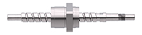
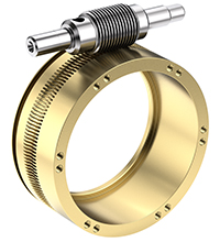
● Transmission : Worm Gear and Ball Screw
● Load Capacity (N) : 29.4, 39.2 and 196
● Material and Surface Treatment : Aluminum Alloy Black Anodized
[Application]
Motorized Rotary Stages are commonly used in various applications in factory automation systems
Product Overview
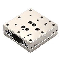
The MISUMI E-RMPG Series Electric Rotary Stage is an economical rotary stage equipped with a two-phase stepper motor. Uses worm gear transmission for 360-degree rotational positioning. Due to localized production and optimized structure, low prices are achieved.
Dimensional Drawing of Rotary

 Material: Aluminum Alloy of Rotary
 Surface Treatment: Black Anodized
Specification Table
| Part Number |  Driver Driver |  Cable Cable | Mechanical Specification | Accuracy Specification | Sensor | ||||||||
 Type Type |  No. No. | Stage Surface (mm) | Travel Distance (°) | Load Capacity (N) | Weight (kg) | Maximum Speed (°/sec) | One-Way Positioning Accuracy | Repetitive Positioning Accuracy | Parallelism (μm) | Limit Sensor | Origin Sensor (ORG1) | ||
| E-RMPG | 40 | A | φ39 | 360 | 29.4 | 0.5 | 25 | Within 0.15° | Within ±0.08° | Within 50 | Not Provided | Provided | |
| 60 | 2 (2m cable) | φ60 | 39.2 | 0.9 | 15 | ||||||||
| 80 | φ79 | 39.2 | 1.1 | 15 | |||||||||
| 100 | 4 (4m cable) | φ99 | 196 | 1.9 | 25 | ||||||||
| 120 | φ119 | 196 | 2.2 | 25 | |||||||||
 Driver: Driver model used in this series: E-DR42B.
■ General Specifications
.jpg)
| No. | 40 | 60 | 80 | 100 | 120 | |
| Reduction Ratio | 1/120 | 1/180 | 1/180 | 1/120 | 1/120 | |
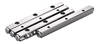
| Guide Rail | Deep Groove Ball Bearing | |||||
| Motor | Shape | 2-Phase Standard Stepper Motor 1.3 A/Phase | 2-Phase Standard Stepper Motor 1.3 A/Phase | 2-Phase High Torque Stepper Motor 1.3 A/Phase | 2-Phase Standard Stepper Motor 2.0 A/Phase | 2-Phase Standard Stepper Motor 2.0 A/Phase |
| Step Angle | 1.8° | |||||
| Resolution (Pulse) Full | ≒0.015° | ≒0.01 | ≒0.01° | ≒0.015° | ≒0.015° | |
| Driver | Power Voltage | DC12 to 50 V | ||||
| Output Current | 0.1 to 2.2 A | |||||
| Pulse Signal Voltage | 5 to 24 V | |||||
| Number of Subdivisions | 200 to 51200 | |||||
| Connector | Part Number | HR10A-10R-12P (Hirose) | ||||
| Receiving side part number | HR10A-10P-12S (Hirose) | |||||
| Sensor Substrate | Limit Sensor | Not Provided | ||||
| Origin Sensor | Provided | |||||
| Power Voltage | 24 V DC±10% | |||||
| Sensor Type | Miniature Photo Sensor RPI-0125 (ROHM) | |||||
| Control Output | NPN Open Collector Output | |||||
| Output Logic | During detection (shading): Output transistor OFF (non-conducting) | |||||
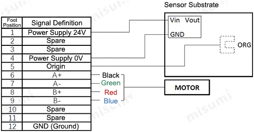
■ Connector Pin Arrangement
.jpg)
■ Wiring Diagram

■ Timing Diagram
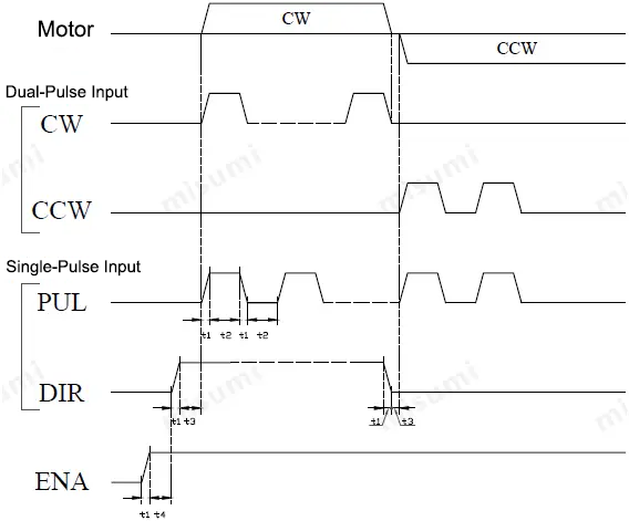
t1<0.1us t2 ≥ 0.9us t3 ≥ 10us
t4: ENA (Enable signal) t4 should be set high at least 10µs before DIR. In general, it is recommended to leave ENA+ and ENA- unconnected.
Product Features
Feature 1: 360-degree continuous rotation angle adjustment.
Feature 2: Optimized structure and lower prices through local production.
Feature 3: By adding positioning holes to the upper and lower bases of the slide table, quick assembly and disassembly are achieved.
Feature 4: The standard driver supports both dual-pulse and pulse + direction control, meeting the needs of various operating conditions.
Usage Method
The E-RMPG series rotary slide table is equipped with a two-phase stepper motor. It needs to be used together with MISUMI's two-phase stepper motor driver, cable, as well as a customer-supplied 24 V power supply and host controller (PLC or motion control card). An example of the connection between each product is shown in the diagram below.
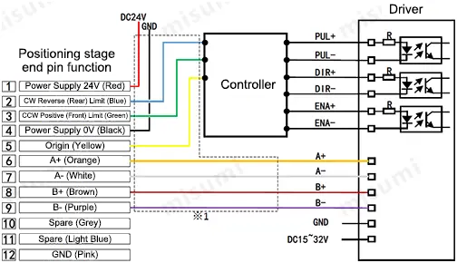

*1 The cables inside the dashed box are 2-meter or 4-meter cables
Precautions
■ Slide Table Operating Environment
Operating environment: 10 to 50°C, 20 to 70%RH (non-condensing)
Recommended environment: 22±5°C, 20 to 70%RH (non-condensing)
Please avoid using the slide table in the following environments
(1) Dusty environments (especially metal powder)
(2) Environments with direct sunlight or heat radiation
(3) Near fire sources
(4) Environments with corrosive or flammable gases
(5) Environments with splashing water or oil
(6) Environments with strong vibration or impact
(7) Environments with organic solvents or high salt content
■About Slide Table Maintenance
There is no unified regular maintenance standard due to differences in grease types and usage environments. Depending on the drive conditions and the type of guide rail, please be sure to check the grease at least once a month.
Application Industries of Rotary
| Electronics/Home Appliance | Automotive | Medical | ||
 |  |  | ||
| Smart phone | Semiconductor | Lithium battery | ||
 |  |  |
Related Products of Rotary
| Economy series X-Axis Motorized Positioning Rotary | Economy series XY-Axis Motorized Positioning Rotary | Economy series Z-Axis Motorized Positioning Rotary |
 |  |  |
| Representative model of Rotary: C-XMBS420-L-A-2 | Representative model of Rotary: C-XYMBS420-L-A-2 | Representative model of Rotary: C-ZMBS420-L-A-2 |
Related Documents
■Driver
Compatible drivers support dual-pulse and pulse + direction control. For installation dimensions and user manual, please refer to: E-DR42B (Chinese only)
Bus driver
For installation dimensions and user manual of the driver, please refer to DM3C-EC522 (Chinese only)
Compatible drivers support dual-pulse and pulse + direction control. For installation dimensions and user manual, please refer to: E-DR42B (Chinese only)
Bus driver
For installation dimensions and user manual of the driver, please refer to DM3C-EC522 (Chinese only)
The motor size for models E-RMPG60-A-2/E-RMPG60-A-4 has changed after June 1, 2024. Please download the latest CAD model when selecting.
If you need other multi-axis combinations, please contact dz@misumi.sh.cn.
Economy Automatic Slide Table Series List
| Electronics/home appliance | Automotive | Medical |