Spring Plungers Stainless Steel

Brand :
MISUMI
Caution
- Download Free! >> Economy Series Catalog (TH-EN-FY25) CLICK here
Product Description
- Spring Plungers Stainless Steel
- C-PJLW and C-PJHW are in the MISUMI economy series ball plungers.
- Body Material: Equivalent Stainless Steel SUS303.
- Pin Material: Stainless Steel SUS303.
- Pin Hardness: 20HRC~
- Spring Material: Stainless Steel SUS304
- The operating Temperature: -30 to 260℃
- Mounting Thread size: 3, 4, 5, 6, 8, 10 and 12 mm.
- Stroke (S): 2, 3, 4, 5 and 10 mm.
- Load Classification: (C-PJLW) Light Load and (C-PJHW) Heavy Load.
- Wrench Hole Shape: Hex.
Product Overview
♢ This series is MISUMI economy series stainless steel spring plunger with coarse threads and mounted from the hexagon socket at the bottom. It is manufactured in China, so its price is reduced significantly, up to 93% less than other similar products.
♢ The spring plunger is also known as the positioning column, ball screw, spring screw, etc. It is a product involving vertical stroke, in which the front pin is pressed till the pin sinks into the body and then the front pin can be ejected through the built-in spring. It can be used in mold release, workpiece lifting and positioning, etc., which can be widely applied in medium and low-precision mechanical devices, fixtures, molds, automation machines, etc.
♢ The spring plunger is also known as the positioning column, ball screw, spring screw, etc. It is a product involving vertical stroke, in which the front pin is pressed till the pin sinks into the body and then the front pin can be ejected through the built-in spring. It can be used in mold release, workpiece lifting and positioning, etc., which can be widely applied in medium and low-precision mechanical devices, fixtures, molds, automation machines, etc.
Dimensional Drawing
Type:C-□□□□
Type:E-L□□□□
Material Specification
| Load Classification | Type | Body | Pin | Spring | ||
 Material Material | Material |  Hardness Hardness | Material | |||
| Stainless Steel Convex Pin | Light Load | C-PJLW C-PJHW | SUS303 | SUS303 | 20HRC~ | SUS304 |
| Heavy Load | ||||||
| Load Classification | Type | Body | Pin | Spring | ||||
| Material | Material | Hardness |  Surface Treatment Surface Treatment | Material | ||||
| Stainless Steel Convex Pin | Ultra Light Load | E-LPJLSW | SUS303 | SUS420F | 40~50HRC | Nickel plating | SUS304 | |
| Ultra Heavy Load | E-LPJLXW | |||||||
| Resin Convex Pin | Ultra Light Load | E-LPJLSK | POM | - | - | |||
| Light Load | E-LPJLK | |||||||
| Heavy Load | E-LPJHK | |||||||
| Ultra Heavy Load | E-LPJXK | |||||||
Specification Table

| Part Number |  Stroke S Stroke S | d | ℓ | L | B | Light Load | Heavy Load | |||||||
 Type Type |  O.D. M O.D. M(Coarse Thread) | Load (N) | Load (N) | |||||||||||
| min. | max. | min. | max. | |||||||||||
| C-PJLW(Light Load) C-PJHW(Heavy Load) | 3 | 3 | 1 | 15 | 15 | 0.9 | 0.3 | 1.5 | 0.6 | 3 | ||||
| 4 | 2 | 1.6 | 1.5 | 15 | 1.3 | 0.5 | 2 | 2 | 10 | |||||
| 4 | 24 | 24 | 1 | 5 | 2 | 10 | ||||||||
| 5 | 3 | 2 | 20 | 20 | 1.5 | 2 | 10 | 5 | 18 | |||||
| 5 | 27 | 27 | 3 | 15 | 8 | 25 | ||||||||
| 6 | 3 | 2.5 | 25 | 25 | 2 | 3 | 15 | 8 | 25 | |||||
| 5 | 30 | 30 | 5 | 20 | 10 | 30 | ||||||||
| 8 | 3 | 3.1 | 25 | 25 | 2.5 | 5 | 20 | 10 | 30 | |||||
| 5 | 27 | 27 | 8 | 25 | 13 | 40 | ||||||||
| 10 | 5 | 3.8 | 30 | 30 | 3 | 5 | 20 | 15 | 45 | |||||
| 12 | 10 | 5.5 | 35 | 43 | 4 | 8 | 25 | 18 | 50 | |||||
kgf=N×0.101972
 The min. load represents the initial load, and the max. load represents the load at the maximum press-in limit of convex pin.There is a groove for front end riveting.No anti-loosening treatment is applied.
| Part Number | Stroke S | d | ℓ | L | B | Ultra Light Load | Light Load | Heavy Load | Ultra Heavy Load | |||||
| Type | O.D. M (Coarse Thread) | Load (N) | Load (N) | Load (N) | Load (N) | |||||||||
| min. | max. | min. | max. | min. | max. | min. | max. | |||||||
| (Stainless Steel Convex Pin) E-LPJLSW E-LPJXW (Resin Convex Pin) E-LPJLSK E-LPJLK E-LPJHK E-LPJXK | 3 | 1.5 | 1 | 15 | 15 | 0.9 | 0.12 | 0.4 | 0.4 | 1.3 | 0.8 | 2.94 | 1.1 | 3.42 |
| 3 | 15 | 15 | 0.12 | 0.4 | 0.2 | 1.3 | 0.6 | 2.93 | 0.8 | 3.41 | ||||
| 4 | 2 | 1.6 | 15 | 15 | 1.3 | 0.27 | 0.65 | 0.9 | 2 | 2 | 8.8 | 6.1 | 13.8 | |
| 4 | 24 | 24 | 0.18 | 0.65 | 0.6 | 2.1 | 1.9 | 8.75 | 5.8 | 13.6 | ||||
| 5 | 3 | 2 | 20 | 20 | 1.5 | 0.4 | 3 | 1.4 | 9.7 | 2.7 | 16.3 | 6.8 | 22 | |
| 5 | 27 | 27 | 0.35 | 3 | 1.1 | 10.3 | 1 | 17.1 | 5.7 | 21.5 | ||||
| 6 | 3 | 2.5 | 25 | 25 | 2 | 1.8 | 3.05 | 6 | 9.8 | 8 | 26.4 | 15.8 | 35.6 | |
| 5 | 30 | 30 | 1.5 | 3.05 | 3.4 | 9.86 | 4.4 | 26.6 | 12.9 | 34.4 | ||||
| 8 | 3 | 3.1 | 25 | 25 | 2.5 | 1.9 | 3.15 | 6 | 9.9 | 14.7 | 27 | 21.9 | 36.3 | |
| 5 | 27 | 27 | 1.4 | 3.15 | 4 | 9.83 | 6.7 | 26.6 | 14.7 | 34.5 | ||||
| 10 | 5 | 3.8 | 30 | 30 | 3 | 1.6 | 4.6 | 5.7 | 14.7 | 8.2 | 45.7 | 24.5 | 58.6 | |
| 10 | 30 | 43 | 1.6 | 4.6 | 4.4 | 14.7 | 6.2 | 45.1 | 19.8 | 58.7 | ||||
| 12 | 5 | 5.5 | 30 | 30 | 4 | 1.7 | 4.7 | 5.8 | 14.7 | 18.2 | 49 | 34.9 | 63.6 | |
| 10 | 35 | 43 | 1.6 | 4.7 | 5 | 14.7 | 8.2 | 49.1 | 25.5 | 63.6 | ||||
| 15 | 35 | 51 | 1.8 | 4.7 | 6.9 | 14.7 | 7.5 | 48.9 | 20.1 | 63.7 | ||||
| 16 | 10 | 8 | 35 | 57 | 5 | 2.8 | 10.8 | 9.2 | 34.2 | 18.9 | 68.6 | 38.7 | 88.4 | |
| 15 | 35 | 57 | 2.6 | 10.8 | 8.6 | 34.4 | 14.4 | 68.6 | 33.9 | 88.1 | ||||
| 20 | 35 | 67 | 2 | 11 | 7.1 | 34.4 | 4.2 | 68.6 | 25.4 | 88.1 | ||||
Product Features
♢ It has complete specifications, which can satisfy the requirements of various sizes, lengths, and loads.
♢ It is made of all stainless steel without painting and coloring, so it is suitable for equipment with high requirements on the surface.
♢The front end has a wrench slot, and the bottom end has a hex socket mounting hole, which facilitates installation.
♢ The stroke can be fine-tuned correspondingly to the screw-in depth.
♢ The spring plunger is a product involving vertical stroke. It can be used in mold release, workpiece lifting and positioning, etc., which can be widely applied in medium and low-precision mechanical devices, fixtures, molds, automation machines, etc.
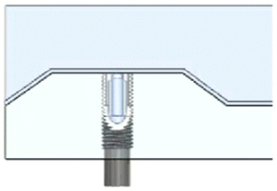
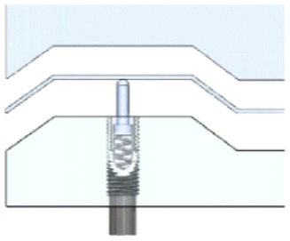
Example of Use
When pressed down

When released

Related Products


