Round Wire Coil Springs, Defection I.D. Referenced, Stainless Steel, Heavy Load
Caution
- This product will be discontinued once stock ran out. The replacement model CLICK here
- Download Free! >>Economy Series Catalog ver2023 (TH-EN)_Part11 CLICK here
Product Description
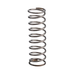
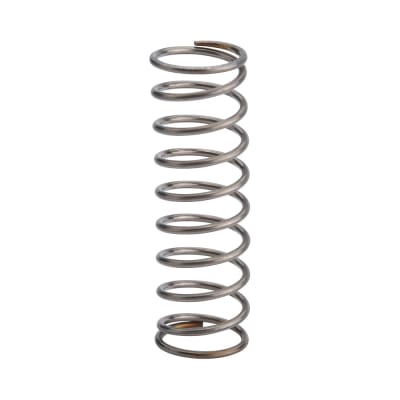
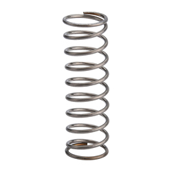
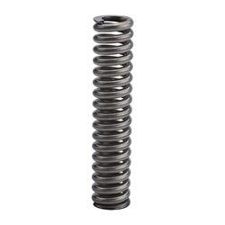
・ Spring type: Round Wire Coil Springs, Heavy Load
・ O.D. Referenced Type is outer diameter prioritized, and the I.D. is a reference value.
・ Spring material: Made of stainless steel SUS304-WPB Spring Constant ±10%
・ Model type: C-VUL, C-VUM, C-NWM, C-NWL
・ Outer diameter D (Ø) [mm]: 4, 5, 6, 8, 10, 12, 13, 16
・ Free length range [mm]: 5, 10, 15, 20, 25, 30, 40
・ End face type: No grinding, With grinding
・ This is an economy item; The price is cheaper than the MISUMI standard product.
Economy Round Wire Coil Springs, Heavy Load
- Engineered for high-load applications without breaking the bank.
- Choose from a wide range of diameters and lengths to fit your needs.
- Built with durable materials for superior performance.
- Tailor the spring’s specifications to match your requirements.
- Designed for precision and longevity in demanding conditions.

MISUMI Standard

Cheaper Price

Product Variety

3D CAD Support
♢Stainless steel springs are also magnetic. Please be careful.
.jpg)
| Inner Diameter D | φ8 or Less  | Free Length L | 50 or Less | ±1mm | |
φAbove 10  | Above 60 | ±2mm | |||
| Material of Round Wire Springs | |||||
| Material SUS304-WPB Spring Constant ±10% | |||||
 C-VUL: Fmax. (allowable displacement) = L×40%The inner diameter standard type gives priority to guaranteeing the inner diameter, while the outer diameter is for reference only.
| Type | Coil O.D. D - Free Length L | Outer Diameter D1 | Wire Diameter d | F max. | N{kgf} max. | Reference | ||||
| Pitch | Solid Length | Total Number of Rolls | ||||||||
| C-VUL | 5 - | 15 | 6.2 | 0.6 | 6 | 5.88 | {0.60} | 2.5 | 4.8 | 7 |
| 20 | 8 | 7.84 | {0.80} | 3.3 | ||||||
| 25 | 6.4 | 0.7 | 10 | 9.80 | {1.00} | 2.3 | 9.1 | 12 | ||
| 6 - | 15 | 7.4 | 0.7 | 6 | 5.88 | {0.60} | 2.1 | 6.3 | 8 | |
| 20 | 8 | 7.84 | {0.80} | 2.9 | ||||||
| 25 | 7.6 | 0.8 | 10 | 9.80 | {1.00} | 2.3 | 10.4 | 12 | ||
| 30 | 12 | 11.76 | {1.20} | 2.7 | ||||||
| 35 | 14 | 13.72 | {1.40} | 3.2 | ||||||
| 40 | 7.8 | 0.9 | 16 | 15.68 | {1.60} | 2.5 | 16.2 | 17 | ||
| 8 - | 20 | 9.8 | 0.9 | 8 | 7.84 | {0.80} | 2.4 | 9.5 | 9.5 | |
| 25 | 10 | 9.80 | {1.00} | 2.9 | ||||||
| 30 | 10.0 | 1.0 | 12 | 11.76 | {1.20} | 2.5 | 14.0 | 13 | ||
| 35 | 10.0 | 1.0 | 14 | 13.72 | {1.40} | 2.9 | 14.0 | 13 | ||
| 60 | 10.4 | 1.2 | 24 | 23.52 | {2.40} | 2.7 | 28.8 | 23 | ||
| 10 - | 20 | 12.0 | 1.0 | 8 | 7.84 | {0.80} | 3.1 | 8.5 | 7.5 | |
| 25 | 10 | 9.80 | {1.00} | 3.8 | ||||||
| 30 | 12.2 | 1.1 | 12 | 11.76 | {1.20} | 3.2 | 12.7 | 10.5 | ||
| 35 | 14 | 13.72 | {1.40} | 3.7 | ||||||
| 40 | 12.2 | 1.1 | 16 | 15.68 | {1.60} | 4.2 | 12.7 | 10.5 | ||
| 12 - | 25 | 14.4 | 1.2 | 10 | 9.80 | {1.00} | 2.9 | 12.6 | 9.5 | |
| 35 | 14 | 13.72 | {1.40} | 4.1 | ||||||
| 55 | 14.8 | 1.4 | 22 | 21.56 | {2.20} | 4.1 | 21.7 | 14.5 | ||
| 16 - | 50 | 19.0 | 1.5 | 20 | 19.60 | {2.00} | 5.9 | 15.8 | 9.5 | |
C-VUM: Fmax. (allowable displacement) = L×35%The inner diameter standard type gives priority to guaranteeing the inner diameter, while the outer diameter is for reference only.| Type | Coil O.D. D - Free Length L | Outer Diameter D1 | Wire Diameter d | F max. | N{kgf} max. | Reference | ||||
| Pitch | Solid Length | Total Number of Rolls | ||||||||
| C-VUM | 5 - | 15 | 6.6 | 0.8 | 5.3 | 15.39 | {1.57} | 2.3 | 6.8 | 7.5 |
| 20 | 6.8 | 0.9 | 7.0 | 20.58 | {2.10} | 1.8 | 11.7 | 12 | ||
| 40 | 7.0 | 1.0 | 14.0 | 41.16 | {4.20} | 3.2 | 14.5 | 13.5 | ||
| 6 - | 15 | 7.8 | 0.9 | 5.3 | 15.39 | {1.57} | 2.3 | 7.7 | 7.5 | |
| 20 | 7.0 | 20.58 | {2.10} | 3.0 | ||||||
| 25 | 8.0 | 1.0 | 8.8 | 25.68 | {2.62} | 2.8 | 11 | 10 | ||
| 30 | 10.5 | 30.87 | {3.15} | 3.3 | ||||||
| 8 - | 20 | 10.2 | 1.1 | 7.0 | 20.58 | {2.10} | 3.3 | 8.8 | 7 | |
| 25 | 8.8 | 25.68 | {2.62} | 4.2 | ||||||
| 30 | 10.2 | 1.1 | 10.5 | 30.87 | {3.15} | 5.0 | 8.8 | 7 | ||
| 35 | 10.6 | 1.3 | 12.3 | 35.97 | {3.67} | 3.5 | 15.6 | 11 | ||
| 40 | 10.6 | 1.3 | 14.0 | 41.16 | {4.20} | 4.0 | 15.6 | 11 | ||
| 10 - | 20 | 12.4 | 1.2 | 7.0 | 20.58 | {2.10} | 4.0 | 8.4 | 6 | |
| 25 | 12.6 | 1.3 | 8.8 | 25.68 | {2.62} | 4.2 | 10.4 | 7 | ||
| 30 | 10.5 | 30.87 | {3.15} | 5.0 | ||||||
| 40 | 13 | 1.5 | 14.0 | 41.16 | {4.20} | 3.8 | 18.8 | 11.5 | ||
| 12 - | 25 | 14.8 | 1.4 | 8.8 | 25.68 | {2.62} | 5.0 | 9.8 | 6 | |
| 16 - | 35 | 19.6 | 1.8 | 12.3 | 35.97 | {3.67} | 5.8 | 14.4 | 7 | |
Calculation method of laps (reference value):Total number of laps = solid length ÷ wire diameter (d)-1; Effective laps=total number of laps-2The number of laps is a reference value. There will be some deviations among batches.The solid length is a reference value. There will be slight differences among batches. Moreover, if it is used under the limit condition of the solid length, it may cause the spring to be deformed or be damaged after using only a limited number of times.Be sure to use within the allowable displacement Fmax.(mm).kgf (load)=N/mm (spring constant)×0.101972×F (displacement); {kgf}=N×0.101972C-NWL: Fmax. (allowable deflection)=L×40%| Type | Coil O.D. D - Free Length L | Outer Diameter D1 | Wire Diameter d | F max. | N{kgf} max. | Spring Constant N/mm{kgf/mm} | Reference Compression Length | |||
| C-NWL | 6.5- | 30* | 8.1 | 0.8 | 12 | 13.7 | {1.4} | 1.1 | {0.12} | 9.6 |
| 35* | 14 | 1.0 | {0.10} | 10.8 | ||||||
| 40* | 16 | 0.9 | {0.09} | 12 | ||||||
| 45* | 18 | 0.8 | {0.08} | 13.2 | ||||||
| 50* | 20 | 0.7 | {0.07} | 14.4 | ||||||
| 8.5- | 35* | 10.5 | 1 | 14 | 20.6 | {2.1} | 1.5 | {0.15} | 10.8 | |
| 40* | 16 | 1.3 | {0.13} | 12 | ||||||
| 45* | 18 | 1.1 | {0.12} | 13 | ||||||
| 16.6- | 60* | 19.8 | 1.6 | 24 | 27.5 | {2.8} | 1.1 | {0.12} | 20 | |
C-NWL: Both ends are ground.C-NWM: Fmax. (allowable deflection)=L×32%| Type | Coil O.D. D - Free Length L | Outer Diameter D1 | Wire Diameter d | F max. | N{kgf} max. | Spring Constant N/mm{kgf/mm} | Reference Compression Length | |||
| C-NWM | 6.5- | 40* | 8.5 | 1 | 12.8 | 20.6 | {2.1} | 1.6 | {0.16} | 17.5 |
| 45* | 14.4 | 1.4 | {0.15} | 19.5 | ||||||
| 50* | 16 | 1.3 | {0.13} | 21 | ||||||
| 13.6- | 35* | 16.8 | 1.6 | 11.2 | 34.3 | {3.5} | 3.1 | {0.31} | 14.4 | |
| 50* | 16 | 2.1 | {0.22} | 18.4 | ||||||
| 60* | 19.2 | 1.8 | {0.18} | 20.8 | ||||||
C-NWM: Both ends are ground.■Spring Constant N/mm {kgf/mm}
| Type | C-VUY | C-VUR | C-VUF | C-VUL | |||||||||
| D | |||||||||||||
| 3 | 0.098 {0.01} | 0.29 {0.03} | 0.49 {0.05} | 0.98 {0.10} | |||||||||
| 4 | |||||||||||||
| 5 | |||||||||||||
| 6 | |||||||||||||
| 8 | 0.196 {0.02} | ||||||||||||
| 10 | |||||||||||||
| 12 | |||||||||||||
| 16 | |||||||||||||
| Fmax. | F=L×Fa% | F=L×60% | F=L×45% | F=L×40% | |||||||||
Select an appropriate Round Wire Springs type according to the actual installation situation, and refer to the published content for the specific inner and outer diameter tolerance values.
* The solid length is a reference value. If it is used under the limit condition of the solid length, the spring may be deformed, or damaged after using only a limited number of times. Therefore, use within the allowable displacement Fmax.(mm).
To increase the usage count, it is recommended to use the spring up to 70% of the allowable displacement Fmax..
Operating temperature of Round Wire Springs
SWP-A……Normal temperature (0~40℃)
Stainless steel……-10~100℃
Spring oil tempered steel wire……Normal temperature (0~40℃)
* If the spring is used under conditions exceeding the above temperature, the load value may decrease due to usage conditions.
* When used in an environment with high and low temperature differences and humidity such as outdoors, it is recommended to choose stainless steel products.
* Heat-resistant springs can also be used. For details, refer to the Plastic Mold Components Catalog.
Stainless steel springs are also magnetic. Please be careful.
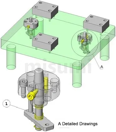
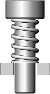
Hole Reference Positioning Mechanism
A Round Wire Springs is mechanism for positioning the workpiece based on the hole reference.
Loosening during positioning can be reduced by using a tapered pin to eliminate the deviation caused by the tolerance of each workpiece hole. Select the compression spring to move from the beginning of the positioning contact with the workpiece.
 |  |  |
| (Economy series) Round Wire Springs - Outer Diameter Standard Stainless Steel, Ultra Light Load, Spring Constant 0.05 to 0.98 N/mm | (Economy series) Round Wire Springs - Inner Diameter Standard Stainless Steel, Light Load, Spring Constant 0.29 to 0.49 N/mm | (Economy series) Round Wire Springs - Outer Diameter Standard Stainless Steel, Ultra Heavy Load, Spring Constant 4.9 to 29.4N/mm |
| Reason for Recommendation: MISUMI Basic Round Wire Springs, Outer Diameter Standard Type, Ultra Light Load Type | Reason for Recommendation: MISUMI Basic Round Wire Springs, Inner Diameter Standard Type, Light Load Type | Reason for Recommendation: MISUMI Basic Round Wire Springs, Outer Diameter Standard Type, Ultra Heavy Load Type |