Jaw Couplings Set Screw Type

Caution
- [Products scheduled to be discontinued]
This products is scheduled to be discontinued. Orders will be accepted until December 28, 2021.
The recommended alternative is the coupling jaw type set screw type (CPJ).
Please check the difference in specifications on the MISUMI-VONA product page. - Download Free! >> Misumi Economy_Series(THA)_Index04_Stepper_Motor_Coupling CLICK here
Product Description
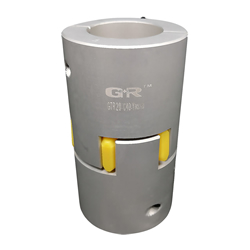
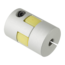
· GCJS/ GCJSLK/ GCJSRK/ GCJSWK Jaw Couplings Set Screw Type.
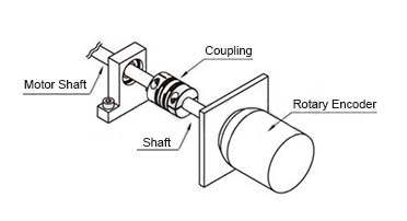
· Jaw Couplings Application: Stepping Motor / Encoder.
· Maximum Rotational Speed Range: 10001~78000 (r/min).
· Maximum Rotational Speed: 10000 (r/min).
· Allowable Angular Misalignment: 1
· Jaw Couplings Body material: Aluminum Alloy.
· The spacer is made of Polyurethane and thus, can absorb vibration efficiently.
· Shaft Tightening Method: Set Screw
· Spacer Selectable Color: Blue, White and Red.
· Operating Temperature: -20°C to 60°C.
· Excellent torque transmission performance has been achieved by press-fitting the spacer into the hub.
Economy Jaw Coupling
- Efficiently absorbs vibrations with polyurethane spacer
- High torque capacity for heavy-duty applications
- Lightweight and compact design for easy installation
- Maintenance-free operation with long service life
- Versatile color options for customization

MISUMI Standard

Cheaper Price

Product Variety

3D CAD Support
Coupling Product Overview
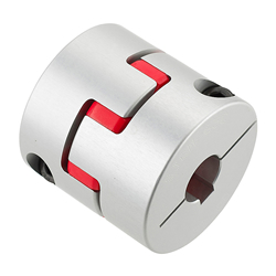
The resin adjusting ring can alleviate the inertia load impact when starting and stopping. Easy to disassemble and assemble.
Applicable motor types: recommended for stepping motors and universal motors.
Coupling Product Feature
Simple structure, no lubrication, convenient repair, easy inspection, maintenance free, and continuous long-term operation.
Urethane elastic parts are wear-resistant and oil-resistant, have large carrying capacity, long service life, and are safe and reliable.
They have excellent damping, cushioning and electrical insulation properties. They have great axial, radial and angular compensation capabilities.
With simple structure, small radial dimension, light weight, and small moment of inertia, they are suitable for medium and high speed applications.
Dimensional Coupling Drawing
| Standard Bore | Keywayed Bore | Material | Surface Treatment | |||||
| d1 (One Side) | d2 (One Side) | d1, d2 (Both Sides) | Hub | Spacer | Set Screw | Hub | Set Screw | |
| GCJS | GCJSLK | GCJSRK | GCJSWK | Aluminum Alloy | Polyurethane | SCM435 | Clear Anodize | Black Oxide |
Coupling Specifications Overview
| Selection | Color | Hardness Shore A |
| BL | Blue | 80 |
| WH | White | 92 |
| RD | Red | 98 |
Coupling Precautions
1. The Coupling allows axis deviation, and transmits rotation angle and torque, but when the axis deviation exceeds the allowable value, vibration will occur or the service life will be drastically reduced.
Be sure to make calibration and adjustment.
2. Axis deviation includes lateral misalignment (parallel error of two axes), angular misalignment (angular error of two axes) and axial amplitude (axial movement of shaft).
Please calibrate and adjust the shaft to ensure that the axis deviation is below the allowable value recorded in the dimension and performance table of each product.
3. The allowable value of axis deviation recorded in the dimension and performance table refers to the situation when either lateral misalignment, angular misalignment or axial amplitude occurs alone. When more than two axis deviations occur at the same time, the corresponding allowable values are halved respectively.
4. Axis deviation not only occurs when assembling to the device, but also is caused by vibration, thermal expansion and bearing wear in operation. Therefore, it is recommended to set the axis deviation below 1/3 of the allowable value.
Example of Use Coupling
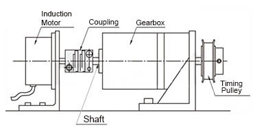
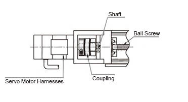
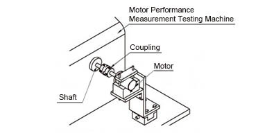
Coupling Usage Method
STEP1 Insert the Coupling
Confirm that the clamping bolt has been unscrewed, and then remove the dust, foreign matter and oil from the shaft and Coupling bore.
Then, when inserting the Coupling into the shaft, please be careful not to put the disc under excessive stress such as compression or tension.
STEP2 Use fixture to adjust
Please use fixture to adjust and fix the concentricity of the left and right hubs of the Coupling with high accuracy.
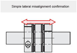
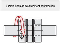
STEP3 Simple lateral misalignment and angular misalignment confirmation
Under the condition of unscrewed bolts, make the Coupling slide axially and confirm its smooth movement.
Then, rotate the Coupling to make sure it moves smoothly.
Lateral misalignment is not allowed for single disc type Coupling, so carry out positioning securely.
STEP4 Installation
Please adjust the shaft insertion amount according to the dimension ℓ in the product catalog, and use a torque wrench to tighten with the specified torque.
* If the specified torque cannot be reached once, please cross fasten the left and right clamps twice or three times.
Coupling Related Products
| (Economy series) GTR plum-shaped Coupling Clamping bolt fixing type/Clamping bolt with keyway type | Coupling Plum-shaped clamping screw fixing type JAAC buffer part material is blind hole (corresponding to LK8-C) | Plum-shaped clamping screw fixing type SJCM |
 |  |  |
Coupling Specification Table
 to
to  . Please specify the shaft bore dia. within the range of d1≤d2.
Part Number (Type· D) D) | - |  Spacer Spacer | - |  d1 d1 | - | d2 |
| GCJS30 GCPJSWK40 | - - | WH BL | - - | 8 12 | - - | 10 15 |
| Part Number | Adjusting ring (Color selection) | d1, d2 selection (But d1≤d2) | L | ℓ | B | C | F | Clamp Screw | |||||||||||
| Type | D | M | Tightening torque (N·m) | ||||||||||||||||
| GCJS | 14 | BL(Blue) WH(White) RD(Red) | 4 | 5 | 6 | 22 | 7 | 6 | 1 | 3.5 | M3 | 0.7 | |||||||
| 20 | 5 | 6 | 6.35 | 8 | 30 | 10 | 8 | 5 | |||||||||||
| 30 | 8 | 10 | 12 | 14 | 35 | 11 | 10 | 1.5 | 5.5 | M4 | 1.7 | ||||||||
| 40 | 10 | 12 | 14 | 15 | 16 | 66 | 25 | 12 | 2 | 12.5 | M5 | 4 | |||||||
| Part Number | Adjusting ring (Color selection) | d1, d2 selection (But d1≤d2) | L | ℓ | B | C | F | Clamp Screw | ||||||
| Type | D | M | Tightening torque (N·m) | |||||||||||
| GCJSLK GCJSRK GCJSWK | 30 | BL(Blue) WH(White) RD(Red) | 10 | 12 | 14 | 35 | 11 | 10 | 1.5 | 5.5 | M4 | 1.7 | ||
| 40 | 10 | 12 | 14 | 15 | 16 | 66 | 25 | 12 | 2 | 12.5 | M5 | 4 | ||
■Characteristic Value
| Part Number | Allowable torque (N·m) | Allowable angular misalignment (°) | Allowable lateral misalignment (mm) | Static torsional stiffness (N·m/rad) | Maximum rotational speed (r/min) | Moment of inertia (kg·m2) | Allowable axial amplitude (mm) | Weight (g) | |||||||
| Type | D | BL | WH | RD | BL | WH | RD | BL | WH | RD | |||||
| GCJS | 14 | 0.7 | 1.2 | 2 | 1.0 | 0.15 | 0.10 | 0.10 | 8 | 14 | 22 | 45000 | 2.1×10⁻⁷ | +0.6 0 | 7.3 |
| 20 | 1.8 | 3 | 5 | 0.20 | 0.15 | 16 | 29 | 55 | 31000 | 1.0×10⁻⁶ | +0.8 0 | 18 | |||
| 30 | 4 | 7.5 | 12.5 | 0.20 | 0.15 | 46 | 73 | 130 | 21000 | 5.9×10⁻⁶ | +1.0 0 | 46 | |||
| 40 | 4.9 | 10 | 17 | 0.15 | 0.10 | 380 | 570 | 1200 | 15000 | 4.0×10⁻⁵ | +1.2 0 | 150 | |||
 The allowable torque varies with temperature.Lateral misalignment, angular misalignment and axial amplitude are all single allowable values. If there are multiple deviations at the same time, the allowable value of each deviation will be reduced to 1/2 of the original value.
| Part Number | Allowable torque (N·m) | Allowable angular misalignment (°) | Allowable lateral misalignment (mm) | Static torsional stiffness (N·m/rad) | Maximum rotational speed (r/min) | Moment of inertia (kg·m2) | Allowable axial amplitude (mm) | Weight (g) | |||||||
| Type | D | BL | WH | RD | BL | WH | RD | BL | WH | RD | |||||
| GCJSLK GCJSRK GCJSWK | 30 | 4 | 7.5 | 12.5 | 1.0 | 0.20 | 0.15 | 0.10 | 46 | 73 | 130 | 21000 | 5.8×10⁻⁶ | +1.0 0 | 45 |
| 40 | 4.9 | 10 | 17 | 0.15 | 0.10 | 380 | 570 | 1200 | 15000 | 3.8×10⁻⁵ | +1.2 0 | 150 | |||
Press the adjusting ring into the main body to assemble.