Linear Guides for Super Heavy Load - Normal Clearance

Caution
- The price will be changed from April 1, 2025. Please see more details in the link >> CLICK here
Product Description
Linear Guides for Super Heavy Load - Normal Clearance
These linear guides or linear slides are factory automation components. They offer a wide variety of sizes to choose from.
[Feature]
● Rail Length Minimum/Maximum (mm.): 100 and 1960
● Assembly Height (mm.): 24, 28, 30, 36, 40, 42 and 45
● Block Type : Standard Block and Wide Block Tapped Hole
● Material: Carbon Steel 56HRC-62HRC
[Application]
It is used in a variety of machines such as CNC machines, 3D printers, measuring instruments, and so on.
Linear Guides for Super Heavy Load, Normal Clearance (Economy Series)
Economy series super heavy load linear guides with normal clearance and Standard grade accuracy. Suited to uses with low accuracy requirements, such as transfer sections and rough positioning.
- Rail: carbon steel S55C. Block: SCM420H. Hardness 58 ~ 62HRC. RoHS compliant.
- Heat-resistant temperature range: -20 ~ 80 °C.
- Blocks and rails cannot be purchased separately.
Product type (part number)
| Material (hardness) | Block type | Rail length Type 1 | Type A 2 | Height (H) B | |
|---|---|---|---|---|---|
| Normal clearance | |||||
| Standard grade | |||||
| 1 block | 2 blocks | ||||
| Carbon steel [Rail: S55C] [Block: SCM420H] (58–62HRC) | Standard block | Standard (fixed) length | C-SHR | C-SH2R | 28 30 40 45 |
| 10 mm increments (specified length) | C-SHRL | C-SH2RL | |||
| Wide block Tapped hole | Standard (fixed) length | C-SHWT | C-SH2WT | 24 30 36 42 | |
| 10 mm increments (specified length) | C-SHWTL | C-SH2WTL | |||
If the desired rail length is not among the standard lengths, select 10 mm increments (specified length).
Heat resistance: -20 to 80°C.
Part number structure
| C-SHRL | 30 | - | 950 | - | (B3)※ |
| A | B | ||||
| Product type (part number) | Rail length (L) | (alteration) | |||
Types and components
- Mounting dimensions are the same for the existing standard and Economy Series items.
The G dimension of the L-specified type differs from the table below.
H and W2 dimensional accuracy
| Type | Accuracy standard | Assembled height (H) | Accuracy (μm) | |
|---|---|---|---|---|
| Standard grade | ||||
| Medium and heavy loads Linear guide | Economy Series | Tolerance of height H | 24–45 | ±120 |
| Pair difference of height H | 40 | |||
| Tolerance of width W2 | ±100 | |||
| Pair difference of width W2 | 40 | |||
- *Viewed from the reference surface
- Pair difference of height is the difference between the minimum and maximum height of multiple blocks combined on one rail.
- Pair difference of width is the difference between the minimum and maximum width between the rail and multiple blocks combined on one rail.
Tolerances of other dimensions
| Size range | Tolerance (mm) | |
|---|---|---|
| Over | Up to | |
| 0.5 | 3 | ±0.1 |
| 3 | 6 | ±0.1 |
| 6 | 30 | ±0.2 |
| 30 | 120 | ±0.3 |
| 120 | 400 | ±0.5 |
| 400 | 1000 | ±0.8 |
| 1000 | 2000 | ±1.2 |
Part numbers and dimensions
| Block Type | H | L | Block dimensions | Rail dimensions | |||||||||||||||||
|---|---|---|---|---|---|---|---|---|---|---|---|---|---|---|---|---|---|---|---|---|---|
| W | L1 | B | C | S×ℓ | L2 | K | T | Cb | Grease nipple | H1 | W1 | W2 | Ca | Counterbore | F | G 3 | |||||
| Mounting hole | E | T1 | d1×d2×h | ||||||||||||||||||
| Standard Block | 28 | 100–1960 (160) | 34 | 55.9 | 26 | 26 | M4×5 | 39.5 | 24.8 | 10.2 | 0.5 | M4×P0.7 | 7 | 9.5 | 13 | 15 | 9.5 | 0.5 | 4.5×7.5×6 | 60 | 20 |
| 30 | 160–1960 (220) | 44 | 74 | 32 | 36 | M5×5 | 54 | 25.4 | 8.2 | 0.5 | M6×P1 | 14 | 6.5 | 16.5 | 20 | 12 | 0.5 | 6×9.5×8.5 | 60 | 20 | |
| 40 | 160–1960 (220) | 48 | 80 | 35 | 35 | M6×6.5 | 59 | 34.2 | 12.15 | 1.0 | M6×P1 | 14 | 11.5 | 20 | 23 | 12.5 | 0.9 | 7×11×9 | 60 | 20 | |
| 45 | 200–1960 (280) | 60 | 95.3 | 40 | 40 | M8×10 | 69.3 | 38 | 11 | 1.0 | M6×P1 | 14 | 11 | 23 | 28 | 16 | 1.0 | 9×14×12 | 80 | 20 | |
| Wide Block | 24 | 100–1960 (160) | 47 | 55.9 | 38 | 30 | M5×8 | 39.5 | 20.8 | 8 | - | M4×P0.7 | 7 | 5.5 | 13 | 15 | 16 | 0.5 | 4.5×7.5×6 | 60 | 20 |
| 30 | 160–1960 (220) | 63 | 74 | 53 | 40 | M6×10 | 54 | 25.4 | 10 | - | M6×P1 | 14 | 6.5 | 16.5 | 20 | 21.5 | 0.5 | 6×9.5×8.5 | 60 | 20 | |
| 36 | 160–1960 (220) | 70 | 80 | 57 | 45 | M8×12 | 59 | 30.2 | 12 | - | M6×P1 | 14 | 7.5 | 20 | 23 | 23.5 | 0.9 | 7×11×9 | 60 | 20 | |
| 42 | 200–1960 (280) | 90 | 95.3 | 72 | 52 | M10×15 | 69.3 | 35 | 15 | - | M6×P1 | 14 | 8 | 23 | 28 | 31 | 1.0 | 9×14×12 | 80 | 20 | |
! Grease nipple: straight type for H24, side-facing type for H28 and above.
! The grease nipple is screw-in type, so its position can be changed.
Align the reference surfaces (the side with the straight groove) of both rail and block correctly when fixing.
Standard (fixed) rail lengths: the table below lists the standard rail lengths for each size.
Lengths not in the table can also be specified in 10 mm increments.
| Height ( H ) | Rail length ( L ) | |||||||||||||||||||||||||||||||
|---|---|---|---|---|---|---|---|---|---|---|---|---|---|---|---|---|---|---|---|---|---|---|---|---|---|---|---|---|---|---|---|---|
| 24 | (100) | 160 | 220 | 280 | 340 | 400 | 460 | 520 | 580 | 640 | 700 | 760 | 820 | 880 | 940 | 1000 | 1060 | 1120 | 1180 | 1240 | 1300 | 1360 | 1420 | 1480 | 1540 | 1600 | 1660 | 1720 | 1780 | 1840 | 1900 | 1960 |
| 28 | (100) | 160 | 220 | 280 | 340 | 400 | 460 | 520 | 580 | 640 | 700 | 760 | 820 | 880 | 940 | 1000 | 1060 | 1120 | 1180 | 1240 | 1300 | 1360 | 1420 | 1480 | 1540 | 1600 | 1660 | 1720 | 1780 | 1840 | 1900 | 1960 |
| 30 | (160) | 220 | 280 | 340 | 400 | 460 | 520 | 580 | 640 | 700 | 760 | 820 | 880 | 940 | 1000 | 1060 | 1120 | 1180 | 1240 | 1300 | 1360 | 1420 | 1480 | 1540 | 1600 | 1660 | 1720 | 1780 | 1840 | 1900 | 1960 | |
| 36 40 | (160) | 220 | 280 | 340 | 400 | 460 | 520 | 580 | 640 | 700 | 760 | 820 | 880 | 940 | 1000 | 1060 | 1120 | 1180 | 1240 | 1300 | 1360 | 1420 | 1480 | 1540 | 1600 | 1660 | 1720 | 1780 | 1840 | 1900 | 1960 | |
| 42 45 | (200) | 280 | 360 | 440 | 520 | 600 | 680 | 760 | 840 | 920 | 1000 | 1080 | 1160 | 1240 | 1320 | 1400 | 1480 | 1560 | 1640 | 1720 | 1800 | 1880 | 1960 | |||||||||
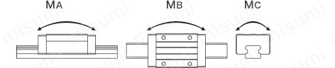
Basic load rating, static allowable moment, mass
kgf=N×0.101972
| H | Basic load rating | Static allowable moment | Mass | ||||||||
|---|---|---|---|---|---|---|---|---|---|---|---|
| C (dynamic) kN | Co (static) kN | 1 block | 2 blocks in contact | Block | Guide rail kg/m | ||||||
| MA N·m | MB N·m | MC N·m | MA N·m | MB N·m | MC N·m | Standard kg | Wide kg | ||||
| 24 28 | 5.1 | 10.2 | 54.2 | 54.2 | 79.9 | 258.4 | 258.4 | 159.8 | 0.20 | 0.20 | 1.32 |
| 30 | 8.6 | 16.8 | 117.3 | 117.3 | 178.6 | 554.6 | 554.6 | 357.2 | 0.29 | 0.40 | 2.28 |
| 36 40 | 11.0 | 20.8 | 158.3 | 158.3 | 254.0 | 756.1 | 756.1 | 508.0 | 0.55 | 0.62 | 3.17 |
| 42 45 | 16.0 | 29.4 | 263.4 | 263.4 | 432.5 | 1248.4 | 1248.4 | 865.0 | 0.85 | 1.42 | 4.54 |
The basic load rating is the same in all 4 directions acting on the block (radial, reverse radial, lateral), so it can be used in any orientation.
Example: allowable load (kN) of H30 under normal operating conditions ⇒ 16.8/2 = 8.4 (approx. 857 kg)
Static safety factor (lower limit of fs)
| Operating conditions | Lower limit of fs |
|---|---|
| Normal operating conditions | 1–2 |
| Smooth running required | 2–4 |
| With vibration or shock | 3–5 |
Allowable load (N) ≤ Co/fs; allowable moment (N·m) ≤ (MA, MB, MC)/fs. fs: static safety factor, Co: basic static load rating, MA, MB, MC: static allowable moments (N·m)
Mounting and handling
Reference surface and mounting direction
The reference surfaces are the ground side of the block and the rail face with the reference mark (large groove). Always align the reference surfaces.
Mounting in any direction is possible, all with the same basic load rating.
The wide block tapped holes allow bolting from below with a screw one size smaller.
Alterations
Alterations are available. Refer to the alteration table for applicable codes, dimensional limits and conditions.
For details, please see the PDF catalog.
Technical reference
Shortest rail length with B3 or B4
| H | B3 (3 blocks) | B4 (4 blocks) |
|---|---|---|
| 24, 28 | 340 | 400 |
| 30 | 400 | 460 |
| 36, 40 | 400 | 520 |
| 42, 45 | 440 | 520 |
Related parts compatibility
| Block shape | Height (H) | Linear guide clamper | Rail mounting holes Cap | Height adjustment block for linear guides <Economy type> | Height adjustment block for linear guides <High-precision type> | |||||
|---|---|---|---|---|---|---|---|---|---|---|
| Knob Type | Clamp Type | General structural steel | Aluminum alloy | S45C equivalent | Aluminum alloy | |||||
| Free side | Reference side | Free side | Reference side | Free side | ||||||
| Standard | 28 | The Economy Series Not usable | - | - | - | - | - | - | - | |
| 30 | PACK-SGLC5 | LGBE28 | ALGBE28 | BETA28 | BETE28 | ABETA28 | ABETE28 | |||
| 40 | PACK-SGLC6 | LGBE33 | ALGBE33 | BETA33 | BETE33 | ABETA33 | ABETE33 | |||
| 45 | - | - | - | - | - | - | - | |||
| Wide | 24 | - | - | - | - | - | - | - | ||
| 30 | PACK-SGLC5 | LGBE28 | ALGBE28 | BETA28 | BETE28 | ABETA28 | ABETE28 | |||
| 36 | PACK-SGLC6 | LGBE33 | ALGBE33 | BETA33 | BETE33 | ABETA33 | ABETE33 | |||
| 42 | - | - | - | - | - | - | - | |||
! No bellows are available for MISUMI linear guides.
Allowable load
Preload and accuracy standards

Normal clearance type
| Radial clearance (μm) | |
|---|---|
| H24 H28 | -4–+4 |
| H30 | -5–+5 |
| H36 H40 | -6–+6 |
| H42 H45 | -7–+7 |

| Dimensional accuracy (μm) | |
|---|---|
| Tolerance of height H | ±120 |
| Pair difference of height H | 40 |
| Tolerance of width W2 | ±120 |
| Pair difference of width W2 | 40 |
| Running parallelism of surface C to surface A | Reference |
| Running parallelism of surface D to surface B | |
Precautions for use
- This is a full-complement ball type. The block has a retainer that keeps the balls from falling out.
If blocks and rails are swapped, radial clearance and accuracy are not guaranteed.
- The reference surface is the side of the block and rail with the wide groove. Always align the reference surfaces.
Rails cannot be joined end to end.
Linear guide accuracy is guaranteed after the rail is fixed (rail screws tightened and pressed against the reference surface).
- Slight rail bending is corrected when the rail is fixed, so it does not affect use.
Others
Packed with lithium soap-based grease (Showa Shell Alvania Grease S2).
Grease nipple: straight type for H24 and H28, side-facing type for H30, H36, H40, H42 and H45.
The grease nipple is screw-in type, so its position can be changed.