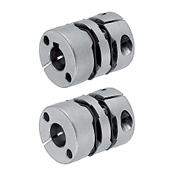
Disc Couplings - Ultra High Torque Clamping (Double Disc) for Servo Motors
Caution
Product Description
· Universal type resistant to small misalignment
· Multiple disc materials support a wide range of uses
· Polyimide - Demonstrates outstanding flexibility and low reaction force even if misaligned, and causes no phase or torque fluctuation
· Well-balanced versatile type featuring excellent carbon FRP-flexibility, transmission torque, and torsional rigidity
· Stainless steel flat spring (SUS) - Inferior flexibility, but high transmission torque and torsional rigidity, so it is ideal for highly responsive servo systems
Disc Couplings, Ultra High Torque, Clamping, Double Disc, for Servo Motors
A versatile double-disc coupling that tolerates small misalignment, with stainless steel flat-spring discs for high transmission torque and torsional rigidity, ideal for responsive servo systems. Choose standard bores or keyway bores on d1, d2 or both.
Types and components
d1 side
d2 side
| Double disc type | |
| MCSLC (standard bore) | MCSLCLK (keyway bore d1) |
| MCSLCRK (keyway bore d2) | |
| MCSLCWK (keyway bores d1, d2) |
Recommended shaft tolerance is h7.
The d1 and d2 tolerances apply before slitting.
Eccentricity, angular misalignment and end play are individual allowable values. When more than one misalignment exists, each allowable value is halved.
| Keyway dimensions | |||||
| Bore dia. d1, d2 | b | t | Nominal key size Dimensions b×h | ||
|---|---|---|---|---|---|
| Standard Dimension | Tolerance | Standard Dimension | Tolerance | ||
| 6–7.9 | 2 | ±0.0125 | 1.0 | +0.1 0 | 2×2 |
| 8–10 | 3 | 1.4 | 3×3 | ||
| 10.1–12 | 4 | ±0.0150 | 1.8 | 4×4 | |
| 12.1–17 | 5 | 2.3 | 5×5 | ||
| 17.1–22 | 6 | 2.8 | 6×6 | ||
| 22.1–24 | 8 | ±0.0180 | 3.3 | +0.2 0 | 8×7 |
For bore dia. 8, 10, 12, 22, the keyway width can be changed.
| Standard bore | Keyway bore | Material | Surface treatment | |||||
|---|---|---|---|---|---|---|---|---|
| d1 (one side) | d2 (one side) | d1, d2 (both sides) | Body | Disc | Hex socket head cap screw | Body | Hex socket head cap screw | |
| MCSLC | MCSLCLK | MCSLCRK | MCSLCWK | Aluminum Die-cast | Stainless steel | SCM435 | Anodized | Black oxide coating |
Part numbers and dimensions
Ordering example
| Type | - | Bore dia. d1 | - | Bore dia. d2 |
|---|---|---|---|---|
| MCSLC40 | - | 10 | - | 15 |
| MCSLCWK40 | - | 10 | - | 12 |
| Type | d1, d2 selection (d1 ≤ d2) Keyway bores are available for bore dia. 6 or more. | d3 | L | ℓ | A | F | Clamp bolt | ||||||||||||||||||
|---|---|---|---|---|---|---|---|---|---|---|---|---|---|---|---|---|---|---|---|---|---|---|---|---|---|
| Type | D | M | Tightening torque (N·m) | ||||||||||||||||||||||
| Double disc type MCSLC MCSLCLK MCSLCRK MCSLCWK | 16 | *4 | 5 | 6 | 6.8 | 23.2 | 7 | 5 | 3 | M2.5 | 1 | ||||||||||||||
| 20 | *4 | 5 | 6 | 6.35 | 7 | 8 | 8.1 | 26 | 7.5 | 6.5 | 3.7 | ||||||||||||||
| 25 | *5 | 6 | 6.35 | 7 | 8 | 9.53 | 10 | 10.4 | 30.2 | 9 | 8.5 | 4 | M3 | 1.7 | |||||||||||
| 32 | 8 | 9.53 | 10 | 11 | 12 | 14 | 15 | 41 | 12.4 | 10 | 6 | M4 | 2.5 | ||||||||||||
| 40 | 8 | 9.53 | 10 | 11 | 12 | 14 | 15 | 16 | 18 | 19.5 | 47 | 15.5 | 13.1 | 7.8 | M5 | 7 | |||||||||
| 50 | 14 | 15 | 16 | 18 | 20 | 22 | 24 | 25 | 53 | 18 | 16.7 | 9 | M6 | 12 | |||||||||||
| Type | Allowable torque (N·m) | Correction Factor | Allowable Angular misalignment (°) | Allowable Eccentricity (mm) | Static torsion Spring constant (N·m/rad) | Max. speed (r/min) | Moment of inertia (kg·m²) | Allowable End play (mm) | Mass (g) | |
|---|---|---|---|---|---|---|---|---|---|---|
| Type | D | |||||||||
| MCSLC MCSLCLK MCSLCRK MCSLCWK | 16 | 0.9 | 5–10 | 2 | 0.15 | 450 | 6000 | 2.7×10^-7 | ±0.2 | 10 |
| 20 | 1.3 | 700 | 5500 | 8.0×10^-7 | 16 | |||||
| 25 | 2.8 | 950 | 5000 | 2.5×10^-6 | ±0.3 | 30 | ||||
| 32 | 5 | 1100 | 4000 | 6.6×10^-6 | ±0.4 | 62 | ||||
| 40 | 9 | 0.2 | 2800 | 3800 | 1.9×10^-5 | ±0.5 | 110 | |||
| 50 | 16 | 3400 | 3500 | 5.0×10^-5 | ±0.6 | 220 | ||||
Moment of inertia is the rotational inertia of the coupling. The larger the value, the greater the inertia.
Alterations
Alterations are available. Refer to the alteration table for applicable codes, dimensional limits and conditions.
For details, please see the PDF catalog.
Technical reference
Coupling selection and handling
Selection procedure
① Select the coupling type using the quick selection table.
| Coupling characteristics | Motor | |||||
| Type | Backlash Zero | High torque | Allowable eccentricity Allowable angular misalignment | Servo | Stepping motor Small servo | General purpose |
| Disc type | ◎ | ◎ | ○ | ◎ | ○ | × |
| Oldham type | × | ◎ | ◎ | × | × | ◎ |
| Slit type | ◎ | ○ | ○ | ○ | ◎ | × |
② Calculate the corrected torque on the coupling (connection to servo or stepping motors, motion control).
Calculate the corrected torque by multiplying the max. motor torque by the correction factor.
- *See the product specifications on the product page for correction factors.
Select a coupling whose allowable torque (shaft slip torque) is at least the corrected torque.
Corrected torque = max. motor torque × correction factor (connection to general motors, power transmission)
- *Calculate the load torque and use 1 to 5 times that value as the corrected torque.
Load torque (N·m) = 9550 × transmitted power (kW) / speed (r/min)
Corrected torque = load torque (N·m) × 1 to 5
③ Check the coupling allowable values. Confirm the moment of inertia meets the machine conditions.
④ Select the bore.
Check that the shaft O.D. is within the bore range of the selected coupling. If not, select a larger size.
⑤ Select the shaft fastening method (clamp, key, friction, etc.) to suit the application.
⑥ Final check
Finally, check the dimension table to confirm it fits the machine.
Safety precautions
Fit a protective cover around the coupling on the machine.