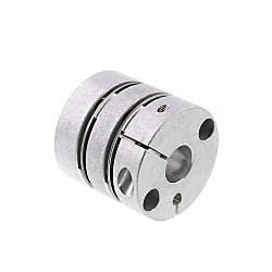
Disc Couplings High Regidity Double Disc, Clamping Type
Caution
- Download Free! >> Misumi Economy_Series(THA)_Index04_Stepper_Motor_Coupling CLICK here
Product Description
· C-SCPW series Disc Couplings High Rigidity Double Disc, Clamping Type
· Type of Coupling: C-SCPW.
· Applicable motor types: recommended for servo motors, stepping motors.
· Maximum Rotational Speed Range: 4001 ~ 10000 (r/min).
· Maximum Rotational Speed: 10000 (r/min).
· Allowable Angular Misalignment: 1.0, 1.2 and 1.5°
· Disc Type: Double Discs.
· Body material: Aluminum Alloy.
· Disc material: Stainless Steel.
· Lock bolt: Steel SCM435 surface treatment Ferro ferric Oxide Protective Film.
· Operating for working in high temperature -80 to 300 °C
· Accessories: Hex socket bolt (Clamping bolt).
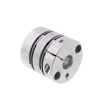
Economy Double Disc Coupling
- High torsional rigidity and zero backlash ensure precision in servo motor operations
- Made from durable aluminum alloy and stainless steel for extended lifespan
- Capable of operating in high temperatures within specified range
- Simple clamping type installation makes setup quick and easy
- Allows for angular, lateral, and axial misalignment, enhancing flexibility

MISUMI Standard

Cheaper Price

Product Variety

3D CAD Support
The disc coupling is composed of several groups of discs (stainless steel thin plates) that are interlaced with two halves of the coupling with bolts, and each group of discs is formed by stacking several pieces.
The disc coupling relies on the elastic deformation of the disc to compensate for the relative displacement of the connected two shafts, which is a high-performance flexible coupling with strong metal components.
It is characterized by compact structure, no backlash, high strength, long service life, no rotation clearance, no influence of temperature and oil pollution, acid resistance, alkali resistance and corrosion resistance.
Applicable motor types: recommended for servo motors, stepping motors and general motors.
■ Differences between MISUMI Economy Series and MISUMI Standard Products (using the same specification diaphragm type as an example)

*Products circulating on the market are similar products randomly purchased by our company from online or offline markets
■Torsional Rigidity
· Test Standard: GB/T10128-2007
· One side of the coupling is in close contact with the drive shaft, while the other side is in close contact with the non-rotating driven shaft. The straight connection section is represented by the unit plane angle from 10% to 100% of the rated torque.
· MISUMI uses A7075 hard aluminum, which has a material hardness more than 1.6 times that of standard A6061 aluminum on the market. The product rigidity is more than twice as high as the market standard, resulting in better motor response.

· Static torsional rigidity: The rigidity of the coupling when subjected to torsional force. The greater the rigidity, the higher the responsiveness of the product.
The rigidity is comparable to the high rigidity SCPW of previous products, and the cost is greatly reduced. The surface has not been oxidized, which may be rough.

| Parts |  Material Material |  Surface Treatment Surface Treatment |  Accessories Accessories |
| Body | Aluminum | - | Hex socket bolt (Clamping bolt) |
| Disc | Stainless Steel | - | |
| Fastening Bolt | SCM435 | Black Oxide Film |
Please order after selecting part number and parameters according to the selection steps
 to
to  .
.Part Number (Type· No.) No.) | - |  d1 d1 | - | d2 |
| C-SCPW34 | - | 10 | - | 14 |
| Part Number | d1, d2 selection (But d1≤d2) | D | d3 | L | ℓ | F | A | Fastening Bolt | ||||||||||||||||||
| Type | No. | M | Tightening torque (N·m) | |||||||||||||||||||||||
| C-SCPW | 16 | 4 | 5 | 6 | 16.6 | 6.5 | 23 | 7.2 | 3 | 5.3 | M2.6 | 1.0 | ||||||||||||||
| 21 | 4 | 5 | 6 | 8 | 21 | 9.5 | 24.5 | 7 | 3.5 | 7 | M2.6 | 1.2 | ||||||||||||||
| 28 | 6 | 6.35 | 8 | 10 | 28 | 12 | 32.2 | 9 | 4 | 9.5 | M3 | 1.7 | ||||||||||||||
| 34 | 6 | 6.35 | 8 | 10 | 11 | 12 | 14 | 34 | 15 | 35 | 9.8 | 5 | 12 | M3 | 1.7 | |||||||||||
| 46 | 8 | 10 | 11 | 12 | 14 | 15 | 16 | 17 | 19 | 46 | 22 | 44 | 12.6 | 6 | 16.5 | M4 | 4.1 | |||||||||
| 55 | 12 | 14 | 15 | 16 | 17 | 19 | 20 | 22 | 24 | 25 | 54.5 | 26 | 55 | 16 | 7 | 20.5 | M5 | 8.2 | ||||||||
■Characteristic Value
| Part Number | Allowable torque (N·m) | Allowable Angular Misalignment (°) | Allowable lateral misalignment (mm) | Static torsional stiffness (N·m/rad) | Maximum Rotational Speed (r/min) | Moment of inertia (kg·m2) | Allowable axial amplitude (mm) | Compensation coefficient | Weight (g) | |
| Type | No. | |||||||||
| C-SCPW | 16 | 0.5 | 1.0 | 0.10 | 500 | 10000 | 4.22×10⁻⁷ | ±0.20 | 1.5 | 11 |
| 21 | 1.0 | 800 | 1.11×10⁻⁶ | 17 | ||||||
| 28 | 1.5 | 1.2 | 0.15 | 3000 | 4.68×10⁻⁶ | 42 | ||||
| 34 | 4.0 | 1.5 | 0.20 | 4800 | 1.10×10⁻⁵ | 65 | ||||
| 46 | 10.0 | 0.25 | 11500 | 4.70×10⁻⁵ | ±0.30 | 151 | ||||
| 55 | 25.0 | 19000 | 1.19×10⁻⁴ | 260 | ||||||
 Static torsional stiffness, moment of inertia and weight are the values at the maximum shaft dia..Lateral misalignment, angular misalignment and axial amplitude are all single allowable values. If there are multiple deviations at the same time, the allowable value of each deviation will be reduced to 1/2 of the original value.For selection criteria and calibration adjustment, refer to >>P.747, 748.
■Shaft slip torque (N·m)
When the shaft slip torque is less than the allowable torque, please use it below the shaft slip torque.| No. | d1, d2 | ||||||||||||||||
| 4 | 5 | 6 | 6.35 | 8 | 10 | 11 | 12 | 14 | 15 | 16 | 17 | 19 | 20 | 22 | 24 | 25 | |
| 16 | 0.5 | 0.5 | 0.5 | - | - | - | - | - | - | - | - | - | - | - | - | - | - |
| 21 | 1.0 | 1.0 | 1.0 | - | 1.0 | - | - | - | - | - | - | - | - | - | - | - | - |
| 28 | - | - | 1.5 | 1.5 | 1.5 | 1.5 | - | - | - | - | - | - | - | - | - | - | - |
| 34 | - | - | 2.5 | 2.5 | 4.0 | 4.0 | 4.0 | 4.0 | 4.0 | - | - | - | - | - | - | - | - |
| 46 | - | - | - | - | 6.0 | 6.0 | 8.0 | 8.0 | 8.0 | 8.0 | 10 | 10 | 10 | - | - | - | - |
| 55 | - | - | - | - | - | - | - | 16 | 16 | 19 | 25 | 25 | 25 | 25 | 25 | 25 | 25 |
1. Strong ability to compensate for misalignment between two axes. Compared with tooth coupling, angular displacement can be doubled. In case of radial displacement, reaction force is small, flexibility is large, and certain axial, radial and angular displacements are allowed.
2. It has obvious shock absorption, no noise and no wear.
3. Can operate safely under conditions of impact and vibration.
4. High transmission efficiency, up to 99.86%. Especially suitable for medium, high speed and high power transmission.
5. Simple structure, light weight, small in size and convenient assembly and disassembly. It can be assembled and disassembled without moving the machine (models with intermediate shaft), and requiring no lubrication.
6. It can accurately transmit the rotational speed without slip, and can be used for transmission of precision machinery
■ Dynamic Torque Fatigue Test
· Check durability by applying performance torque at the maximum angle of deflection
· MISUMI economy core components use Japanese stainless steel diaphragms and assembly screws. Through strict internal assembly management, each component is precisely assembled, greatly improving product lifespan.
■ Test Conditions
· Load Torque: Allowable Torque
· Eccentricity: Maximum eccentricity
· Deflection Angle: Maximum Eccentric Angle
· Test cycle: Forward and reverse rotation every 15 minutes (total 10 million rotations)
■ Test Result

*Products circulating on the market are similar products randomly purchased by our company from online or offline markets. The test data are obtained through testing by our company, which are for reference only
STEP1 Insert the coupling
Make sure the clamping bolts are loosened, then remove any dust, foreign matter, or oil from the shaft and the coupling bore.
Then, when inserting the coupling into the shaft, please be careful not to put the disc under excessive stress such as compression or tension.
STEP2 Use a jig for adjustment
Please use a jig to precisely adjust and secure the concentricity of the left and right hubs of the coupling.
STEP3 Simple Confirmation of Eccentricity and Angular Misalignment
While the bolts are loosened, slide the coupling axially to ensure smooth movement.
Then, rotate the coupling to make sure it moves smoothly.
Lateral misalignment is not allowed for single disc type coupling, so carry out positioning securely.STEP4 Installation


Please adjust the shaft insertion amount according to the product catalog ℓ dimension, and tighten with a torque wrench to the specified torque.
*If the specified torque cannot be reached once, please cross fasten the left and right clamps twice or three times.
1. The coupling allows axis deviation, and transmits rotation angle and torque, but when the axis deviation exceeds the allowable value, vibration will occur or the service life will be drastically reduced.
Be sure to make calibration and adjustment.
2. Axis deviation includes lateral misalignment (parallel error of two axes), angular misalignment (angular error of two axes) and axial amplitude (axial movement of shaft).
Please calibrate and adjust the shaft to ensure that the axis deviation is below the allowable value recorded in the dimension and performance table of each product.
3. The allowable value of axis deviation recorded in the dimension and performance table refers to the situation when either lateral misalignment, angular misalignment or axial amplitude occurs alone. When more than two axis deviations occur at the same time, the corresponding allowable values are halved respectively.
4. Axis deviation not only occurs when assembling to the device, but also is caused by vibration, thermal expansion and bearing wear in operation. Therefore, it is recommended to set the axis deviation below 1/3 of the allowable value.


