Post-Assembly Panel Holder for HSDP Clamp

Caution
- Due to Air shipment restrictions, the maximum allowable cargo length is not over than 2,600 mm. If the item exceeds 2600mm, the lead time will be approximately 1.5 months. Please contact MISUMI for more information.
Product Description
This product is used as a set with the HSDP clamp for post-insertion panel hold.
Dimensional Drawing of Panel Mounts
・For Panel Mounts 3mm thick
For 5 Series
HSDA5
・For Panel Mounts 5mm thick
For 6 Series
HSDA6
For 8 Series
HSDA8
・For Panel Mounts 5mm thick
For 8-45 series
HSDA8-45
For 10 series
HSDA10
Specification Table of Panel Mounts
| Panel Mounts Model | − | length |
| HSDA5 | − | 800 |
・To check the latest price, please click the "Check Price" button after confirming the model number.
| Panel Mounts Model | Length specified in 1mm increments | Compatible frame (series) | Applicable panel thickness | |
| Type | No. | |||
| HSDA | 5 | 100 to 3000 | 5 Series | 3 |
| 6 | 6 Series | 5 | ||
| 8 | 8 Series | |||
| 8-45 | 8-45 series* | |||
| 10 | 10 Series | |||
[ ! ]Please check with WOS if the displayed quantity is exceeded.
Additional Work of Panel Mounts
| Panel Mounts Model | − | length | − | (CTW45) |
| HSDA5 | − | 800 | − | CTW45 |
| 3 | Shipped on the same day |
| Alteration | Code | Spec. |
| Panel Mounts hold groove upper part cut at 45 degrees | CTW45 | Cut the top of the Panel Mounts hold groove at a 45-degree angle. [ ! ]Use tapping joints to connect frames together.
|

Product Overview (Panel Clamp Overview) of Panel Mounts
Compatible with joint bracket connections only.

■ Product type
| Panel clamp | Economy Panel Clamp | Post-insertion Panel Mounts clamp (used as a set) | Groove cover resin soft | |
| Panel Mounts | clamp | |||
|
|
|
|
|
| EPDM rubber, olefin elastomer | PVC Polyvinyl chloride | aluminum | EPDM rubber | polyethylene |


Groove fitting of Panel Mounts
■ Overview
This method involves fitting the panel into the groove in the frame.
It does not require drilling holes in the panel and does not require screws, so it is recommended for those who prioritize design. It can only be used when assembling with
screw joints, center joints, single joints, first-in-first-out double joints, and last-in-first-out double joints.
| Usage example | Electrical equipment covers, FA equipment covers, safety covers |
|---|---|
| Easy panel removal | △ |
| Gap between the frame | be |
| Appearance | usually |
| Panel size calculation | easy |
| Panel thickness (mm) | 3mm (5 series) |
| 5mm (6/8/8-45 series) |
■ Installation method
The panel size must be determined so that the fasteners do not interfere with the Panel Mounts.
(1) Fasten the three frames together with blind joint parts.
(2) Insert the panel into the frame groove.
(3) Cut the panel clamp or inverted groove cover to the frame size and insert it into the gap.

Insert the panel clamp into the 6 series gap.
Parts selection method of Panel Mounts
| Components | ①Aluminum frame | ②Aluminum frame | ③Blind joint | ④Panel | ⑤Panel clamp |
|---|---|---|---|---|---|
|
|
|
|
| |
| Model example | HFS6-3030-400-LCV-RCV | HFS6-3030-340-LDH-RDH | HSJNS6 | ACAE-356-356-5-FS6-ES6-JS6-KS6 | HSCP5HN-S-6 |
| quantity | 2 | 2 | 4 | 1 | 1 |


①Aluminum frame: Additional machining for blind joint (single joint: wrench hole machining)
②Aluminum frame: Additional machining for blind joint (single joint: D-hole machining)
③Blind joint
④Panel: Additional cutting
Thickness:3mm (5 series), 5mm
(6/8/8-45 series) . 1mm clearance on each side. Panel vertical width (A) = frame internal dimension (X) + frame groove internal depth - clearance (1mm x 2). Panel horizontal width (B) = frame internal dimension (L2) + frame groove internaldepth - clearance (1mm x 2).
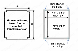
Groove internal depth
| 5 Series | 6 Series | 8 Series | 8-45 Series |
|---|---|---|---|
| 6mm x 2 | 9mm x 2 | 12.5mm x 2 | 13mm x 2 |

Additional
aluminum frame cutout for blind joints
| Alterations | Aluminum frame blind joint cutout |
 | |
| Code | F□□・E□□・J□□・K□□ |
| Spec. | We provide relief cuts for blind joints on aluminum frames. [ ! ]Play for expansion and contraction of plates due to temperature differences is not taken into consideration. [ ! ]The longitudinal direction of the cutout is always on the A dimension side. [ ! ]Applies only to T=3 and 5 Designation methodFS 6
Frame type Joint Type Notch position (from the diagram above) |
| ¥/1Code | 200/corner |

| Joint-specific cutout shape | Simple joint kit | Single joint kit Screw joint kit | Pre-assembled double joint kit | Center joint | Post-insertion double joint | ||
| Single joint kit standard type | Single joint kit narrow type, screw joint kit | Standard Type | Eccentric nut type | ||||
(Example 1) (Example 2)  In Example 2, no cutouts are required in the panel. |  |  [ ! ]The illustration shows the single joint kit narrow type. |  |  | (Example 1) (Example 2)  |  | |
A = L1 (400-30-30) + groove depth (9mm x 2) - clearance (2mm) = 356mm
B = L2 (340) + groove depth (9mm x 2) - clearance (2mm) = 356mm
Thickness 5mm
6 Series Single Joint Cutout (-FS6-ES6-JS6-KS6)
↓
ACAE-356-356-5-FS6-ES6-JS6-KS6
⑤ Panel clamp (post-insertion Panel Mountser/Panel Mountser clamp is also acceptable)
Length: ①Inside frame vertically -1mm, ②Inside frame horizontally -17mm (-1mm if corners are cut at 45 degrees)
Thickness: Select a panel clamp with a thickness equal to the width of the frame groove minus the thickness of the panel.
Additional processing: Cut corners at 45 degrees (you can also cut them yourself with scissors, etc.)
Insert the panel clamp into the 6 series gap.
Usage example: It can be
easily cut with scissors or a cutter . Cutting the corners at a 45-degree angle will improve the appearance.
<After assembly>
Select the panel clamp model based on the thickness of the aluminum frame and panel.
| series | Groove Width | Panel Thickness | |
|---|---|---|---|
| 3mm | 5mm | ||
| 5 | 6mm | HSCP3H HSCPF3H NSCP3H | HSCP1H HSCPF1H NSCP1H |
| 6 | 8mm | HSCP5H HSCPF5HN NSCP5HN | HSCP3H HSCPF3H NSCP3H |
| 8 | 10mm | HSCP7H HSCPF7H NSCP7H | HSCP5H HSCPF5HN NSCP5HN |
| 8-45 | 10mm | HSCP7H HSCPF7H NSCP7H | HSCP5H HSCPF5HN NSCP5HN |
| Representative model | color | Panel Mounts Material | Heat-resistant temperature (℃) | ||
|---|---|---|---|---|---|
| HSCP3H | black | EDPM rubber | -40 to +120 | ||
| HSCPF3H | Light gray | Olefin elastomer | -20 to +80 | ||
| NSCP3H | Light gray | PVC Polyvinyl chloride | -25 to +80 | ||
*If you use a post-installation Panel Mounts and a Panel Mounts clamp instead of a panel clamp, you can attach the panel after assembling the frame.
*The groove cover resin soft can be inserted into the groove by turning it over and inserting it into the groove.
Before installation
After installation
Panel Mounts side
Clamp side
· Panel Mounts can be installed after the frame is assembled.
· Panel Mounts can be replaced without disassembling the frame.
[ ! ]Panel Mountsing clamps can be cut with a cutter.
(Installation procedure)
HFS6-3030
①Insert the Panel Mounts into the groove in the frame.
HFS6-3030
②Insert the panel onto the Panel Mounts.
HFS6-3030
3) Insert the Panel Mounts clamp into the gap.
・Example of using a groove cover
・Example of using the frame support cover
■Panel Mounts Features of HSCL/HSCLS (soft resin)
Compared to HSCA/HSCAS (resin), it is softer.
It is easy to insert into grooves and can be easily cut with scissors.