Timing Pulleys - XL Type

Caution
- Please note that the swaged flange options, NFC, RFC, and LFC, are not reflected in the CAD data.
- For customers who are selecting timing pulley with tapped holes on the tooth surface. Depending on the shaft bore diameter selected by the customer, the accessory set screw may protrude and interfere with the belt. Please check whether the set screw protrudes from the bottom of the pulley root on the 3D preview or CAD. If it protrudes, please consider alteration SLH "Set screw length change" or changing to shape B. Thank you for choosing this product.
- Please check the content on our website as the PDF does not contain the most up-to-date information.
Product Description
[Material]
· Pulley: Aluminum alloy, S45C equivalent, SUS304
· Flange: Aluminum alloy, SPCC, SUS304
[Surface treatment]
· Clear anodize, black anodize, hard clear anodize (firm hardness 300HV~), electroless nickel plating, black iron oxide coating
[Related Products]
· Timing belt Timing Belt, Long Timing Belts-Iron Rubber, Open End Belt Iron Rubber, Open End Belts/Polyurethane/Chloroprene Rubber
· Idler Idler with Teeth Center Bearing, Idler with Teeth Both Sides Bearing, Idler - Backside Tensioning Center Bearing, Idler - Backside Tensioning Both Sides Bearing
Dimensional Drawing
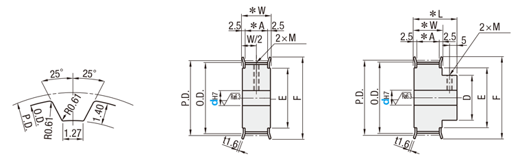
■XL
● Pulley Shape
Tooth Profile
(ISO Standard Rack Dimensions)
Shape A
Shape B
[ ! ]
[ ! ]
| Dimension Range | Tolerance (mm) | |
| Over | or Less | |
| 0.5 | 3 | ±0.1 |
| 3 | 6 | |
| 6 | 30 | ±0.2 |
| 30 | 120 | ±0.3 |
(Medium Class).
[ ! ] For aluminum and stainless steel flanges, the flange thickness is 1.5.
[ ! ] The tolerance of the tap position dimension from the boss end face and pulley end face is ±0.3.
[ ! ] Shaft Bore Specs. H (Round hole), V or F (Stepped Hole), Y (Both Sides Stepped Hole) and WB (Two-stepped Hole) do not have tapped holes.
[ ! ] Unless otherwise specified except for teeth and F dimensions, the dimension tolerance conforms to JIS B 0405 Class m.
[ ! ] Surface treatment may not be applied to shaft bores.
[ ! ] No standard value is specified for chamfering of d dim.
H Round Hole
P Round Hole + Tap
N New JIS Keyway + Tap
C Old JIS Keyway + Tap
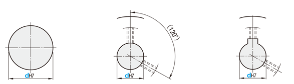
[ ! ] For A-Shape pulley, the screw holes are set at around 120° to keep away from peaks.
[ ! ] Specify NK10 when selecting "New JIS Keywayed Bore" + "Shaft Bore Diameter 10" + "Keyway Width 4.0 mm".
[ ! ] The difference between part number N10 and NK10 is the machining dimensions. See the table below, "New JIS Keyway Dimension Tolerance," for details.
[ ! ] The position of the keyway and the phase of the teeth are not guaranteed.
V Stepped Hole
F Stepped Hole (Counterbored Hole on the Hub Side)
Y Both Ends Stepped Hole
WB Two-stepped Hole
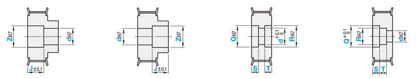
[ ! ] Z-V(d) ≥ 2
[ ! ] 2.0 ≤ J ≤ W-2.0
[ ! ] Applicable to Shape B only
[ ! ] Z-F(d) ≥ 2
[ ! ] 2.0 ≤ J ≤ L-2.0
[ ! ] Applicable to Shape A only
[ ! ] Q-Y(d) ≥ 2
[ ! ] R-Y(d) ≥ 2
[ ! ] S+T ≤ W-3.0
[ ! ] S (T) ≥ 3.0
[ ! ] Applicable to Shape A only
[ ! ] Q-R ≥ 2
[ ! ] R-WB(d) ≥ 2
[ ! ] S+T ≤ W-3.0
[ ! ] S (T) ≥ 3.0
| dH7 Shaft Bore I.D. | M (Coarse) | Accessory Set Screws | Number of Accessories Included |
| 4 | M3 | M3 × 3 | 2 |
| 5 to 12 | M4 | M4 × 3 | |
| 13 to 17 | M5 | M5 × 4 | |
| 18 to 35 | M6 | M6 × 5 |
| mm | Nominal | |||
| XL025 | XL031 | XL037 | XL050 | |
| A | 7.5 | 9.0 | 11.0 | 14.0 |
| W | 12.5 | 14.0 | 16.0 | 19.0 |
| L | 21.0 | 23.0 | 25.0 | 28.0 |
| Nominal(N,C) | dH7 |
| 8 to 10(K) | +0.015 0 |
| 11 to 18 | +0.018 0 |
| 19 to 30 | +0.021 0 |
| 31 to 50 | +0.025 0 |
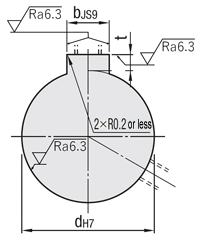
| Nominal(N) | bJS9 | t | ||
| 8 to 10 | 3 | ±0.0125 | 1.4 | +0.1 0 |
| 10K to 12 | 4 | ±0.0150 | 1.8 | |
| 13 to 17 | 5 | 2.3 | ||
| 18 to 22 | 6 | 2.8 | ||
| 23 to 30 | 8 | ±0.0180 | 3.3 | +0.2 0 |
| 31 to 38 | 10 | |||
| 39 to 44 | 12 | ±0.0215 | ||
| 45 to 50 | 14 | 3.8 | ||
| Nominal(C) | bJS9 | t | ||
| 10 to 12 | 4 | +0.022 +0.010 | 1.5 | +0.1 0 |
| 15 to 20 | 5 | 2 | ||
| Shape | Hole | ||||||
| H | P | N(C) | V | F | Y | WB | |
| A | ○ | ○ | ○ | ○ | ‐ | ○ | ○ |
| B | ○ | ○ | ○ | ○ | ○ | ‐ | ‐ |
| Type | Belt Width | [ M ] Material | [ S ] Surface Treatment | [ A ] Accessory Set Screws | ||||
| 6.4 mm (1/4 in) | 7.9 mm (5/16 in) | 9.5 mm (3/8 in) | 12.7 mm (1/2 in) | Pulley | Flange | |||
| XL025 | XL031 | XL037 | XL050 | |||||
| ATP | ● | ● | ● | ● | Aluminum alloy | Aluminum alloy | Clear Anodize | SUS304 |
| BTP | ● | ● | ● | ● | Black Anodize | |||
| KTP | ● | ● | ● | ● | Hard Clear Anodize | |||
| NTP | ● | ● | ● | ● | Electroless nickel plating | |||
| MTP | ● | - | ● | ● | S45C Equivalent | SPCC | - | SCM435 (Black Oxide) |
| MTPB | ● | - | ● | ● | Black Oxide Coating | |||
| MTPP | ● | - | ● | ● | Electroless nickel plating | |||
| STP | ● | ● | ● | ● | SUS304 | SUS304 | - | SUS304 |
[ ! ] Due to vibrations during transportation, the set screw may become detached from the main body.
[ ! ] For orders with no flange, please specify the alteration NFC.