Miniature Linear Guides - Short Blocks, Light Preload / Slight Clearance

Caution
- We will stop the sale of Carbon Steel Miniature Linear Guide in 2021. Please see below for the details.
End of Sale Notification for MISUMI Carbon Steel Miniature Linear Guide Products - [Express Service Resumed] L dimension usage restrictions have been removed.
Product Description
Short Block Type of industry-standard specifications. 20% more compact than standard blocks. Manufactured by SURUGA Production Platform, Co., Ltd. SURUGA Production Platform has developed its business based around accurate processing technology capable of micron level accuracy.
SURUGA's accurate mechanical parts are also used in fields employing cutting edge technologies such as the aerospace and automobile industries.
Type (Part Number)
| Sufrace Treatment Material (Hardness) | Rail Length Type 1 | Number of Blocks 2 | Preload/Accuracy A | Lubrication Unit (MX) B | Height (H) C | Grease D 3 | ||
|---|---|---|---|---|---|---|---|---|
| Light Preload | Slight Clearance | |||||||
| Precision Grade | High Grade | Standard Grade | ||||||
| No Surface Treatment Stainless Steel [SUS440C Equivalent] (56HRC or more) | Standard length (Selectable) | 1 | SSEBSV | SSEBS | SSEBSZ | Blank: None -MX: Provided | 8 10 13 16 | Blank: Standard G: Grease G L: Grease L Y: Grease Y H: Grease H |
| 2 | SSE2BSV | SSE2BS | SSE2BSZ | |||||
| 1 mm increments (Dimension Configurable) | 1 | SSEBSLV | SSEBSL | SSEBSLZ | ||||
| 2 | SSE2BSLV | SSE2BSL | SSE2BSLZ | |||||
| Low Temperature Black Chrome Plating Stainless Steel [SUS440C Equivalent] (56HRC or more) | Standard length (Selectable) | 1 | - | RSEBS | - | None | ||
| 2 | - | RSE2BS | - | |||||
| 1 mm increments (Dimension Configurable) | 1 | - | RSEBSL | - | ||||
| 2 | - | RSE2BSL | - | |||||
1If the desired rail length is not available in the standard length (selectable), please specify the length in 1 mm increments (dimension configurable).
2If a 3- to 4-block product is desired, please select a part number for a 1-block product and specify "B3 (3 blocks)" or "B4 (4 blocks)" for alterations.
3*Only standard grease is available for the MX (with lubrication unit) type.
[ ! ] Heat resistance temperature is -20 to 80°C.
[ NG ] Blocks and rails cannot be purchased separately.Part Number Configuration
Type | Height H | Grease | - | Rail Length L | - | Alterations | |||
A B | C | D | |||||||
Drawing
[ ! ] For L Dimension Configurable Type, G dimensions differ from those shown in the table below.
Tolerance
| L Dimension Range | Tolerance |
|---|---|
| 25 ≤ L ≤ 400 | 0 -0.8 |
| 400 < L ≤ 1000 | 0 -1.0 |
| Type | Accuracy Standards | Assembly Height(H) | Precision(μm) | ||||
|---|---|---|---|---|---|---|---|
| Precision Grade | High Grade | Standard Grade | |||||
| No Surface Treatment | Low Temperature Black Chrome Plating | ||||||
| Miniature Linear Guide | Height H Tolerance | 6 to 20 | ±10 | ±20 | +30 -20 | ±20 | |
Pair Variation of Height H | 7 | 15 | 15 | 40 | |||
Width W2 Tolerance | ±15 | ±25 | ±25 | ±25 | |||
Pair Variation of Width W2 | 10 | 20 | 20 | 40 | |||
| Dimension Range | Tolerance (mm) | |
|---|---|---|
| Over | or Less | |
0.5 | 3 | ±0.1 |
3 | 6 | ±0.1 |
6 | 30 | ±0.2 |
30 | 120 | ±0.3 |
120 | 400 | ±0.5 |
400 | 1000 | ±0.8 |
1000 | 2000 | ±1.2 |
Class m (intermediate)
[ ! ]The precision of low temperature black chrome plated Miniature Linear Guides is as shown above.
The sliding resistance is higher than that of Standard Type: approx. 1.2 N or lower.
Specification Table
| Part Number | L 4 | Block Dimensions | Rail Dimensions | |||||||||||||||
|---|---|---|---|---|---|---|---|---|---|---|---|---|---|---|---|---|---|---|
| Type | MX | H | W | L1 | B | S × ℓ | L2 | K | Cb | W1 | W2 | H1 | Ca | Counterbored Hole | F | G 5 | ||
| 1 Block | 2 blocks | d1 × d2 × h | ||||||||||||||||
| SSEBS SSEBSV SSEBSZ SSEBSL SSEBSLV SSEBSLZ RSEBS RSEBSL | SSE2BS SSE2BSV SSE2BSZ SSE2BSL SSE2BSLV SSE2BSLZ RSE2BS RSE2BSL | — | 8 | 40 to 310 (55) | 17 | 19.6 | 12 | M2 × 2.5 | 9.6 | 6.5 | 0.3 | 7 | 5 | 4.7 | 0.3 | 2.4 × 4.2 × 2.3 | 15 | 5 |
| Blank: None -MX: Provided | 10 | 35 to 635 (75) | 20 | 22.9 | 15 | M3 × 3 | 11.9 | 7.8 | 0.3 | 9 | 5.5 | 5.5 | 0.3 | 3.5 × 6 × 3.5 | 20 | 7.5 | ||
| 13 | 45 to 970 (95) | 27 | 27 | 20 | M3 × 3.5 | 13 | 10 | 0.5 | 12 | 7.5 | 7.5 | 0.5 | 3.5 × 6 × 4.5 | 25 | 10 | |||
| 16 | 70 to 990 (110) | 32 | 32.7 | 25 | M3 × 4 | 17.7 | 12 | 0.5 | 15 | 8.5 | 9.5 | 0.5 | 3.5 × 6 × 4.5 | 40 | 15 | |||
5For L Dimension Configurable Types, both ends of the rail are evenly cut. G dim. resulting from this cutting process will differ from those indicated on the above table.
!H8 comes with rail mounting bolts. H8: For the hex socket head cap screws (M2 × 6)
Not included with other dimensions.
!Correctly match the datum planes (the side with the straight grooves) of both the rail and block. For details, see "Mounting and Handling" below.
Standard Rail Length (Selectable) List
The table below lists the standard rail lengths for each size. Please select the rail length from here.
Lengths not listed in the table below can be custom specified in 1 mm increments.
| Height | Rail Length | |||||||||||||||||||||||||||||||||||||
| (H) | (L) | |||||||||||||||||||||||||||||||||||||
| 8 | (40) | 55 | 70 | 85 | 100 | 115 | 130 | 145 | 160 | 175 | 190 | 205 | 220 | 235 | 250 | 265 | 280 | 295 | 310 | |||||||||||||||||||
| 10 | (35) | (55) | 75 | 95 | 115 | 135 | 155 | 175 | 195 | 215 | 235 | 255 | 275 | 295 | 315 | 335 | 355 | 375 | 395 | 415 | 435 | 455 | 475 | 495 | 515 | 535 | 555 | 575 | 595 | 615 | 635 | |||||||
| 13 | (45) | (70) | 95 | 120 | 145 | 170 | 195 | 220 | 245 | 270 | 295 | 320 | 345 | 370 | 395 | 420 | 445 | 470 | 495 | 520 | 545 | 570 | 595 | 620 | 645 | 670 | 695 | 720 | 745 | 770 | 795 | 820 | 845 | 870 | 895 | 920 | 945 | 970 |
| 16 | (70) | 110 | 150 | 190 | 230 | 270 | 310 | 350 | 390 | 430 | 470 | 510 | 550 | 590 | 630 | 670 | 710 | 750 | 790 | 830 | 870 | 910 | 950 | |||||||||||||||
! The dimensions in ( ) are not available for the standard 2-block type.
Basic Load Rating, Allowable Static Moment, Mass, Friction Resistance (Required Thrust), Sliding Resistance (Seal Resistance)
kgf = N × 0.101972
| Height (H) | Basic Load Rating 6 | Allowable Static Moment | Mass | |||||||
|---|---|---|---|---|---|---|---|---|---|---|
| C (Dynamic) kN | Co (Static) kN | Block 1 pc. | Block 2 pcs. in close contact 7 | Block kg | Guide Rail kg/m | |||||
| MA N⋅m | MB N⋅m | MC N⋅m | MA N⋅m | MB N⋅m | MC N⋅m | |||||
| 8 | 0.79 | 1.27 | 1.9 | 1.6 | 4.6 | 12.4 | 12.4 | 9.2 | 0.008 | 0.19 |
| 10 | 1.16 | 1.68 | 3.1 | 2.6 | 7.9 | 23.4 | 23.4 | 15.8 | 0.015 | 0.31 |
| 13 | 1.63 | 2.38 | 5.2 | 4.4 | 14.8 | 38.1 | 38.1 | 29.6 | 0.025 | 0.61 |
| 16 | 3.08 | 4.23 | 12.3 | 10.3 | 32.6 | 85.4 | 85.4 | 65.2 | 0.05 | 1.02 |
7The allowable static moment when two blocks are in close contact is not a guaranteed value but a reference value.
- The guideline for the allowable load and allowable moment of the linear guide is the value obtained by dividing each value (above table) by the static safety factor fs (below table).
[Example] Allowable load (kN) for H10 under normal driving conditions: 1.68/2 = 0.84 (Approx. 86 kg) - The actual friction resistance (required thrust) when using a linear guide will vary depending on the load and other factors.
Static Safety Factor (Lower Limits of fs)
| Condition of Use | Lower Limits of fs |
|---|---|
| For normal operating condition | 1 to 2 |
| When smooth running performance is required | 2 to 4 |
| When there is vibration or impact | 3 to 5 |
Allowable Load (N) ≤ Co/fs
Allowable Moment (N⋅m) ≤ (MA, MB, MC)/fs
fs: Static Safety Factor Co: Basic Static Load Rating
MA, MB, MC: Allowable Static Moment (N⋅m)
![[Figure]Allowable Static Moment](https://content.misumi-ec.com/image/upload/t_msmwm_wyg/v1/p/jp/product/wysiwyg/wysiwygcommon/pic_glossary_10.png)
・In linear guides, the rolling elements perform rolling motion, resulting in lower frictional resistance compared to sliding guides.
However, this can vary depending on the applied load, speed, and the characteristics of the lubricant.
Especially when a moment load is applied or preload is applied, friction resistance increases. Although seal resistance varies depending on the seal lip press-fit allowance
and the condition of the lubricant, it is not proportional to load and always shows a constant value. Friction resistance is obtained by the following formula.
F=μ・w+f
μ: Dynamic Friction Coefficient
w: Load (N)
f: Sliding Resistance (Seal Resistance)
| Type | Dynamic Friction Coefficient (μ) |
| Miniature Linear Guide | 0.004 to 0.006 |
| Linear Guides for Medium Load | 0.002 to 0.003 |
Condition: Miniature linear guide (standard rail) assembly height (H): 10: Sliding resistance (seal resistance): 0.5 (N)
Dynamic Friction Coefficient (μ):0.005
Load: 150(N)
F (Friction Resistance)=0.005×150+0.5=1.25(N)
■ Datum Plane and Mounting Direction
- Datum plane has the Datum Plane Mark (groove) on the block and rail (Fig. A). Be sure to match the datum planes for use.
- The mounting direction shown in Fig. B is acceptable. All the basic load ratings are same.
| Fig. A | Fig. B |
 |  |
■ Precautions for Use
- Although the retainer (wire) prevents the balls from derailing, care must be taken when attaching and removing the block.
- Radial clearances and accuracies are not guaranteed if the blocks and rails are interchanged from the original set combinations.
- Rails cannot be connected end to end.
- The accuracy of Linear Guides is guaranteed after mounting the rail (after fastening screws on the rail and pushing it onto the datum plane).
Minor bending of the rail will be adjusted by being secured and will not affect the performance.
■ About Grease
- Filled with a standard grease: lithium soap based grease (Multemp Grease PS2 by KYODO YUSHI) before shipment.
The standard grease when selecting the lubrication unit MX is (ENEOS Corporation Tufflix MP2). - Greasing with a different brand of grease is not recommended. Please use the same brand of grease.
- Apply grease directly to the rail. After applying, move the block to let the grease absorb.
- The miniature type does not come with a grease fitting or greasing hole.
- When lubrication unit MX is selected: When the datum plane is in front, the grease fitting is attached in the direction shown in the diagram below.


| Advantages of Lubrication Unit MX: The oil-impregnated porous core part has been built into the product. Provides long term maintenance-free operation. Reduces maintenance cost. Most suitable where the design does not allow lubrication. |
Alterations
| Code | Alterations | Specifications | Notes | ||||||||||
|---|---|---|---|---|---|---|---|---|---|---|---|---|---|
| MC | Change rail counterbore holes to tapped holes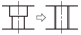 | ·Changes the guide rail mounting holes from counterbored holes to tapped holes. | ! Not applicable for H dim. 8 ≥ 131, H dim. 10 ≥ 276, H dim. 13 ≥ 471 or H dim.16 ≥ 671 ! See the table below for the tapped hole dimensions after change.
| ||||||||||
| LLC RLC | LLC: Left End Cut RLC: Right End Cut  | ·Cuts rail ends. ·Rails are cut with the engraved side as front (datum plane as back). (as shown in the image on the left) ·Please refer to the table below for the length of the rail to be cut.
| !The overall length will be shortened by the amount of cutting. Example: The L dimension of SSEBS13-95-LLC is 90 mm. !Applicable only to Selectable Type (standard rail length). !Not applicable to H8. !Not applicable to L35 of H10 and L45 of H13. | ||||||||||
| B3 B4 | B3: Additional Block (Total 3 pcs.) B4: Additional Block (Total 4 pcs.) 3-Block Specifications  4-Block Specifications | ·It will be shipped with 3 (4) blocks installed. ·There is a minimum length limit for the L dimension (rail length). Please refer to the table below "Shortest Selectable Rail Lengths for B3/B4." | !Please specify the part number for one block. (× SSE2BS10-215-B4) |

| H | B3 (3 blocks) | B4 (4 blocks) |
| 8 | 85 | 100 |
| 10 | 95 | 135 |
| 13 | 120 | 145 |
| 16 | 150 | 190 |
App. Example
Short Block
Standard Block