Flanged Linear Bushings - Single, Opposite Counterbored Hole

Caution
- Due to the change in the bonding method, traces of milky-white adhesive remain on the joint between the flange and the outer cylinder, but there is no change in the catalog specifications.
- About the appearance change of Flanged Linear Bushings CLICK here
- Except for MX Lubrication Units, MISUMI Linear Bushings are applied with anti-rust oil harmless to lubricants. After cleaning and drying the bushings, grease application is recommended before use.
- Recommended Cleaning Method: Ultrasonic cleaning machine or white kerosene
- Delivery times for some of our products may be delayed as national government authorities have imposed limit of capacity at our production sites.
Product Description
Flanged Linear Bushings - Single, Opposite Counterbored Hole
The linear bushing supports and guides a load, enabling smooth and accurate linear motion along a specified path. It provides a variety of sizes to choose from.
[Feature]
● Support Shaft Diameter Minimum/Maximum (mm.): 3 and 50
● Overall Length Minimum/Maximum (mm.): 10 and 100
● Flange Shape : Round Flange, Square Flange and Compact Flange
● Material:
- Outer Cylinder - SUJ2 Equivalent or SUS440C Equivalent
- Ball - SUJ2 Equivalent or SUS440C Equivalent
[Application]
It is used in industrial machinery such as conveyor systems, packaging machines, and robotic equipment.
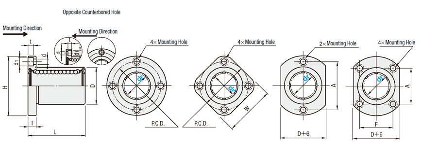
Dimensional Drawing
Product Specifications
| Counterbored Holes | Type | Outer Cylinder | Balls | Retainer | Operating Ambient Temperature | [A] Accessory | ||||
| Round Flange | Square flange | Compact Flange | [M] Material | [H] Hardness | [S] Surface Treatment | [M] Material | [M] Material | |||
| Opposite Counterbored | LHZR | LHZS | LHZC | SUJ2 Equivalent | 58HRC or more | — | SUJ2 Equivalent | Plastic (Duracon M90 Equivalent) | −20 to 80°C | Seal [M] Material Nitrile Rubber (-20 to 120°C) |
| Standard | LHFR | LHFS | LHFC | |||||||
| LHFR−N No Seal | LHFS−N No Seal | LHFC−N No Seal | ||||||||
| LHFRF | LHFSF | LHFCF | Stainless Steel (SUS) | −20 to 110°C | ||||||
| LHFRR | LHFSR | LHFCR | Low Temperature Black Chrome Plating | SUS440C Equivalent | Plastic (Duracon M90 Equivalent) | −20 to 80°C | ||||
| LHFRM | LHFSM | LHFCM | Electroless Nickel Plating | |||||||
| LHFRM−N No Seal | LHFSM−N No Seal | LHFCM−N No Seal | ||||||||
| LHFRMF | LHFSMF | LHFCMF | Stainless Steel (SUS) | −20 to 110°C | ||||||
| SLHFR | SLHFS | SLHFC | SUS440C Equivalent | 56HRC or more | — | Plastic (Duracon M90 Equivalent) | −20 to 80°C | |||
| SLHFRS | SLHFSS | SLHFCS | Stainless Steel (SUS) | −20 to 120°C | ||||||
Specification Table
| Part Number | ||
| LHFR8 LHFR−N10  LHFRR8 LHFRR8 LHFRR10L LHFRR10L | (No Seal) (Low Temperature Black Chrome Plating) (L Type Greased) | [ ! ] Alternative grease types available. |
| dr | D Tolerance | L | H | T | d | d1 | t | P.C.D. | W | F | A | Eccentricity (Max.) * 1 | Balls Rows | Perpendicularity * 2 | Basic Load Rating | Mass (g) | |||||||
| Tolerance | Surface Treatment Not Provided | Surface Treatment Provided | Tolerance | C (Dynamic) N | Co (Static) N | Round Flange | Square flange | Compact Flange | |||||||||||||||
| 3 | 0 −0.008 | 7 | 0 −0.011 | 0 −0.015 | 10 | ±0.3 | 19 | 3.5 | 2.5 | 4.5 | 2.1 | 13 | 15 | — | 13 | 0.008 | 4 | 0.008 | 69 | 105 | 7 | 5.1 | 6 |
| 4 | 8 | 12 | 20 | 14 | 16 | — | 14 | 88 | 127 | 8 | 6.2 | 7 | |||||||||||
| 5 | 10 | 15 | 25 | 5 | 3.5 | 6 | 3.1 | 17 | 20 | — | 17 | 167 | 206 | 17 | 13 | 14 | |||||||
| 6 | 0 −0.009 | 12 | 0 −0.013 | 0 −0.018 | 19 | 28 | 20 | 22 | — | 20 | 0.012 | 0.012 | 206 | 265 | 24 | 18 | 21 | ||||||
| 8 | 15 | 24 | 32 | 24 | 25 | — | 24 | 265 | 380 | 37 | 29 | 33 | |||||||||||
| 10 | 19 | 0 −0.016 | 0 −0.021 | 29 | 40 | 6 | 4.5 | 7.5 | 4.1 | 29 | 30 | — | 29 | 372 | 549 | 72 | 52 | 64 | |||||
| 12 | 21 | 30 | 42 | 32 | 32 | — | 32 | 412 | 598 | 76 | 57 | 68 | |||||||||||
| 13 | 23 | 32 | 43 | 33 | 34 | — | 33 | 510 | 784 | 88 | 72 | 81 | |||||||||||
| 16 | 28 | 37 | 48 | 38 | 37 | 22 | 31 | 775 | 1180 | 120 | 104 | 112 | |||||||||||
| 20 | 0 −0.010 | 32 | 0 −0.019 | 0 −0.025 | 42 | 54 | 8 | 5.5 | 9 | 5.1 | 43 | 42 | 24 | 36 | 0.015 | 5 | 0.015 | 882 | 1370 | 180 | 145 | 167 | |
| 25 | 40 | 59 | 62 | 51 | 50 | 32 | 40 | 6 | 980 | 1570 | 340 | 300 | 325 | ||||||||||
| 30 | 45 | 64 | 74 | 10 | 6.6 | 11 | 6.1 | 60 | 58 | 35 | 49 | 1570 | 2740 | 470 | 375 | 388 | |||||||
| 35 | 0 −0.012 | 52 | 0 −0.022 | 0 −0.030 | 70 | 82 | 67 | 64 | 38 | 55 | 0.020 | 0.020 | 1670 | 3140 | 650 | 560 | 575 | ||||||
| 40 | 60 | 80 | 96 | 13 | 9 | 14 | 8.1 | 78 | 75 | 45 | 64 | 2160 | 4020 | 1060 | 880 | 913 | |||||||
| 50 | 80 | 100 | 116 | 98 | 92 | 56 | 80 | 3820 | 7940 | 2200 | 2000 | 2037 | |||||||||||
* 2. Perpendicularity of D to flange mounting surface.
[ ! ] Anti-rust oil is applied at the time of delivery.
[ ! ] No seal supplied for dr = 3 or 4.
" ! " There are 2 engraving types for products without seals. Example: Part Number: For LHFR-N10, it will be either LHFR-N10 or LHFR10-N.
By selecting the grease below, change to the product with grease coating is available.
| Type | Product Name | Main Features |
| A Type | Alvania Grease S2 (by Showa Shell Sekiyu) | General-purpose grease suitable for various grease lubrication locations. |
| Y Type | AFF (Made by THK Co., Ltd.) | Grease with less particles, stable rolling resistance, and excellent fretting resistance. |
| G Type | LG2 (Made by NSK Ltd.) | Grease with less particles, excellent wear and rust resistance. |
| L Type | ET-100K (Made by KYODO YUSHI Co., Ltd.) | Superior heat resistance and oxidation stability. Also high adhesion and cohesion with limited splash or leakage. |
| H Type | FGL (Lubriplate) | Suitable for lubrication of equipment used in food, beverage and pharmaceutical industries. (NSF H-1 Reg. No. 043534) |
| Item | Conditions | Unit | Measurement Method | A Type | Y Type | G Type | L Type | H Type |
| Thickener | — | — | — | Lithium Type | Lithium Type | Lithium Type | Aromatic Diurea | Aluminum Complex Soap |
| Base Oil | — | — | — | Mineral Oil | Fine Synthetic Oil | Mineral Oil + Synthetic Hydrocarbon Oil | Ether Synthetic Oil | USP White Oil |
| Base Oil Kinematic Viscosity | 40°C | mm2/s | JIS K2220 23 | 131 | 100 | 32 | — | 105 (ASTMD-445) |
| 100°C | 12.2 | — | 5.4 | — | 11.5 (ASTMD-445) | |||
| Worked Penetration | — | — | JIS K2220 7 | 283 | 315 | 199 | 280 | 310 (ASTMD-217) |
| Dropping Point | — | °C | JIS K2220 8 | 181 | 220 | 201 | 260 < | 238 (ASTMD-217) |
| Evaporation Amount | 99°C × 22 hr | wt% | JIS K2220 10 | 0.2 | 0.7 | 1.4 | — | 0.27 (ASTMD−972) |
| Oil Separation | 100°C × 24 hr | wt% | JIS K2220 11 | 2.4 | 2.6 | 0.8 | 1.2 | 2.1 (ASTMD−1742) |
| Operating Temp. | In Air | °C | — | -25 to 120 | -40 to 120 | −20 to 70 | −40 to 200 | −12 to 177 |
Selection Supporting Information
Fitting of Shaft O.D. and Bushing I.D.
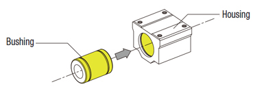
Fitting of Bushing O.D. and Housing I.D.
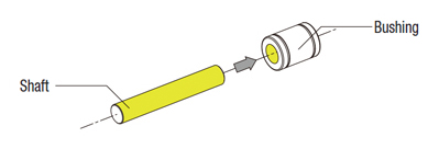
| Dimensions (mm) | Linear Bushings Single Type (LMU) I.D. Tolerance | Shaft (SFJ) O.D. Tolerance (g6) | ||||||||
| 0 | ⌀3 to 5 | ⌀6 to 16 | ⌀20 to 30 | ⌀35 to 50 | ||||||
| -0.001 | ||||||||||
| -0.002 | ⌀3 | |||||||||
| -0.003 | ||||||||||
| -0.004 | ⌀4 to 6 | |||||||||
| -0.005 | ⌀8 to 10 | |||||||||
| -0.006 | ⌀12 to 18 | |||||||||
| -0.007 | ⌀20 to 30 | |||||||||
| -0.008 | ||||||||||
| -0.009 | ⌀35 to 50 | |||||||||
| -0.010 | ||||||||||
| -0.011 | ||||||||||
| -0.012 | ||||||||||
| -0.013 | ||||||||||
| -0.014 | ||||||||||
| -0.015 | ||||||||||
| -0.016 | ||||||||||
| -0.017 | ||||||||||
| -0.018 | ||||||||||
| -0.019 | ||||||||||
| -0.020 | ||||||||||
| -0.021 | ||||||||||
| -0.022 | ||||||||||
| -0.023 | ||||||||||
| -0.024 | ||||||||||
| -0.025 | ||||||||||
| Product | Customer's design | |||
| I.D. dr | Outer Dia. D | Housing Dia. | ||
| Tolerance | Tolerance H7 | |||
| 3 | 7 | 0 -0.009 | 7 | +0.015 0 |
| 4 | 8 | 8 | ||
| 5 | 10 | 10 | ||
| 6 | 12 | 0 -0.011 | 12 | +0.018 0 |
| 8 | 15 | 15 | ||
| 10 | 19 | 0 -0.013 | 19 | +0.021 0 |
| 12 | 21 | 21 | ||
| 13 | 23 | 23 | ||
| 16 | 28 | 28 | ||
| 20 | 32 | 0 -0.016 | 32 | +0.025 0 |
| 25 | 40 | 40 | ||
| 30 | 45 | 45 | ||
| 35 | 52 | 0 -0.019 | 52 | +0.030 0 |
| 40 | 60 | 60 | ||
| 50 | 80 | 80 | ||
Bushing and Housing will be clearance fit.
Technical Information
■Calculation of Life
- When the linear systems are in motion with loads, rolling surfaces and races are subject to repeated stress and will show stress-induced scaly damages called "flaking". The total run distance of a linear system until this flaking first appears is the life of a linear system.
Rated life can be calculated using the formula below from the basic dynamic load rating and the actual load applied to the linear bushings.
C: Basic Dynamic Load Rating (N)
P: Applied Load (N)
fw: Load Factor (Refer to Table-4)
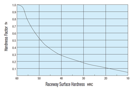
fH : Hardness Factor (Refer to Fig.-1)
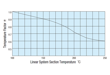
fT : Temperature Factor (Refer to Fig.-2)
fC : Contact Factor (Refer to Table-3)
If the ample hardness of the shafts are not obtained, the allowable loads are reduced and the life will be shortened.
| Number of bushings on one shaft | Contact Factor fc |
|---|---|
| 1 | 1.00 |
| 2 | 0.81 |
| 3 | 0.72 |
| 4 | 0.66 |
| 5 | 0.61 |
| Conditions of Use | fw |
|---|---|
| No external shocks or vibrations when running in low speed: 15 m/min. or less | 1.0 to 1.5 |
| No excessive external shocks or vibrations when running in medium speed: 60 m/min. or less | 1.5 to 2.0 |
| External shocks and vibrations given when running in high speed: 60 m/min. or more | 2.0 to 3.5 |
Life in hours can be obtained by calculating travel distance per hour.
If the stroke length and number of strokes are constant, life in hours can be calculated using the following formula.
n1: Reciprocating Cycles per Minute (cpm)
Cautions/Prohibitions
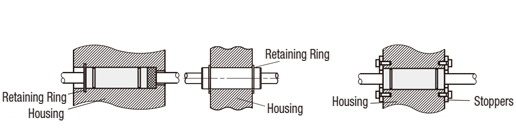
(1) When mounting Linear Bushings and Housings, use Retaining Rings (Snap Rings), Stoppers, etc.
(2) Linear Bushings are not suitable for rotating motion or usage with repetitive insertion and extraction of shafts. Forced use may cause damage.

(3) If large moment load (offset load) is to be applied, Short/Single Type Linear Bushings are not suitable. Use of Double Type or Multiple Linear Bushings is recommended.
(4) When assembling with linear shafts, forcing the shaft into the bushing with angular misalignment may cause the ball retainers to deform and balls to fall out. Be sure to align the centers and insert the shaft gently.
