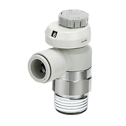
Speed Controller With Indicator, Elbow Type / Universal Type, AS-FS Series
Caution
- Some of the items are scheduled to be discontinued as of end of March in 2023. The manufacturer keep the items produced but they are not available with Misumi.
There are not the replacement items and the plan to resumption of sale. Please check the quotation and order screen for details. - See catalog for specification details.
- Product images may be representative images. Refer to the catalog for shape details.
Product Description
Speed controller with push-lock type knob.
[Features]
・ It contributes to "reduction of labor-hours" and "reduction of setting error" by numerical value management of flow rate
・ Numerical value management is possible with a scale window
・ It is an arrangement that considers visibility and can be selected from 4 directions
・ Flow rate reproducibility, tube removal and insertion are improved, and electroless nickel plating specifications are standardized
[10-series clean series]
・ Suitable for clean environment
・ It prevents dust generation in the cleanroom
Speed Controller With Indicator Window Allowing Flow Rate To Be Controlled Numerically

The numerical indication of flow rate helps to reduce labor time and setting errors.

Universal type: indicator window directions of 90°/270° also available.
Speed Controller With Indicator, Elbow Type / Universal Type, AS-FS Series Specifications
| Type | Series | Cylinder side Port size | Applicable tubing outer diameter Metric size | Applicable tubing outer diameter Inch size |
|---|---|---|---|---|
| Elbow type | AS12□ 1FS to 42□ 1FS | M5 × 0.8 10-32UNF R.NPT.G 1/8 to 1/2 | ø2 to ø16 | ø1/8" to ø1/2" |
| Universal type | AS13□ 1FS to 43□ 1FS | M5 × 0.8 10-32UNF R.NPT.G 1/8 to 1/2 | ø3.2 to ø12 | ø1/8" to ø1/2" |
| Usable fluids | Air |
|---|---|
| Proof pressure | 1.5 MPa |
| Max. operating pressure | 1 MPa |
| Min. operating pressure | 0.1 MPa |
| Ambient and fluid temperature | -5 to 60℃ (no freezing) |
| Applicable tubing material | Nylon, soft nylon, polyurethaneNote), FEP, PFA |
Specifications
Note) Use caution at the max. operating pressure when using soft nylon or polyurethane tubing.
| Model | AS1□□1FS-M5□ | ||
|---|---|---|---|
| Tube outer diameter | Metric size | ø2 | ø3.2 ø4 ø6 |
| Inch Size | - | ø1/8" ø1/4" ø5/32" | |
| C values: Sonic conductance dm3/(s·bar) | Free flow | 0.2 | 0.3 |
| Controlled flow | 0.2 | 0.3 | |
| b values: Critical pressure ratio | Free flow | 0.3 | 0.4 |
| Controlled flow | 0.2 | ||
Flow Rate And Sonic Conductance (Model number: AS1□01FS□-M5□, AS1□11FS□-M5□)
*10-32UNF has the same specification as M5.
* C and b values are for controlled flow with the needle fully open and free flow with the needle fully closed.

Needle Valve: Flow Rate Characteristics (Model number: AS1□01FS□-M5□, AS1□11FS□-M5□)
*-U10/32 has the same specification as M5.
Features of this product

4 indicator window directions offer improved visibility.

Larger push-lock type knob.

Easier to insert and remove tubes.
AS-FS Series (Model number: AS22□1FS-02-06S) / Conventional product (Model number: AS22□1F-02-06) for reference.

Indicator window:
allows numerical indication to be checked easily.

Improved reproducibility of flow rate:
Stable knob position when fully closed (no flow rate) onto the contact face stopper (rotating stopper). Minimal flow rate variation depending on the number of knob rotations.

4 indicator window directions offer improved visibility.

Inspection and maintenance labor can be reduced by selecting the indicator window direction suitable for the operating conditions. This also improves flexibility of equipment design.
Outline Drawing And Dimensions For This Product

Speed Controller With Indicator, Elbow Type, AS-FS Type dimensional drawing
Seal method: Gasket seal
Thread type: M5, 10-32UNF

Indicator window direction: 0° side view

Indicator window direction: 180°
| Model | d | T | H | D1 | D3 | L1 | L2 | L3 | L4Note 1) | ANote 2) | M | W1 | W2 | X | Y | Weight g | ||
|---|---|---|---|---|---|---|---|---|---|---|---|---|---|---|---|---|---|---|
| Unlock | Lock | Unlock | Lock | |||||||||||||||
| AS12□1FS□-M5E-02 | 2 | M5 × 0.8 10/32UNF | 8 | 5.8 | 9.4 | 15.8 | 20.3 | 16.9 | 39 | 36.5 | 35 | 33.5 | 11.9 | 13.6 | 15.1 | 5.5 | 9.6 | 7 |
| AS12□1FS□-U10/32E-02 | ||||||||||||||||||
| AS12□1FS□-M5E-23 | 3.2 | 7.2 | 17.2 | 21.7 | 13.3 | |||||||||||||
| AS12□1FS□-U10/32E-23 | ||||||||||||||||||
| AS12□1FS□-M5E-04 | 4 | 8.2 | ||||||||||||||||
| AS12□1FS□-U10/32E-04 | ||||||||||||||||||
| AS12□1FS□-M5E-06 | 6 | 10.4 | 18.6 | 23.1 | 16.5 | 8 | ||||||||||||
| AS12□1FS□-U10/32E-06 | ||||||||||||||||||
Metric size
| Model | d | T | H | D1 | D3 | L1 | L2 | L3 | L4Note 1) | ANote 2) | M | W1 | W2 | X | Y | Weight (g) | ||
|---|---|---|---|---|---|---|---|---|---|---|---|---|---|---|---|---|---|---|
| Unlock | Lock | Unlock | Lock | |||||||||||||||
| AS12□1FS□-M5E-01 | 1/8" | M5 × 0.8 10/32UNF | 8 | 7.2 | 9.4 | 17.2 | 21.7 | 16.9 | 39 | 36.5 | 35 | 33.5 | 13.3 | 13.6 | 15.1 | 5.5 | 9.6 | 7 |
| AS12□1FS□-U10/32E-01 | ||||||||||||||||||
| AS12□1FS□-M5E-03 | 5/32" | 8.2 | ||||||||||||||||
| AS12□1FS□-U10/32E-03 | ||||||||||||||||||
| AS12□1FS□-M5E-07 | 1/4" | 11.2 | 18.6 | 23.1 | 16.5 | 8 | ||||||||||||
| AS12□1FS□-U10/32E-07 | ||||||||||||||||||
Inch size
Note 1) Reference dimensions
Note 2) Reference dimensions of threads after installation

Universal Type dimensional drawing
Seal method: Gasket seal
Thread type: M5, 10-32UNF

Side view
| Model | d | T | H | D1 | D2 | D3 | L1 | L2 | L3 | L4 | L5 | A | M | W1 | Y | Weight (g) | ||
|---|---|---|---|---|---|---|---|---|---|---|---|---|---|---|---|---|---|---|
| Unlock | Lock | Unlock | Lock | |||||||||||||||
| AS13□1FS1-M5E-23 | 3.2 | M5 × 0.8 10/32UNF | 8 | 7.2 | 9.6 | 9.4 | 11.6 | 19.4 | 17.5 | 33.8 | 39 | 36.5 | 35 | 33.5 | 13.3 | 13.6 | 9.6 | 7 |
| AS13□1FS1-U10-32/23 | ||||||||||||||||||
| AS13□1FS1-M5E-04 | 4 | 8.2 | 11.5 | 19.8 | ||||||||||||||
| AS13□1FS1-U10/32-04 | ||||||||||||||||||
| AS13□1FS1-M5E-06 | 6 | 10.4 | 20.9 | 20.4 | 36.6 | 8 | ||||||||||||
| AS13□1FS1-U10/32-06 | ||||||||||||||||||
Metric size
| Model | d | T | H | D1 | D2 | D3 | L1 | L2 | L3 | L4 | L5 | A | M | W1 | Y | Weight (g) | ||
|---|---|---|---|---|---|---|---|---|---|---|---|---|---|---|---|---|---|---|
| Unlock | Lock | Unlock | Lock | |||||||||||||||
| AS13□1FS1-M5E-01 | 1/8 | M5 × 0.8 10/32UNF | 8 | 7.2 | 9.4 | 9 | 17.2 | 19.8 | 17.5 | 33.8 | 39 | 36.5 | 35 | 33.5 | 13.3 | 13.6 | 9.6 | 7 |
| AS13□1FS1-U10/32-01 | ||||||||||||||||||
| AS13□1FS1-M5E-03 | 5/32 | 8.2 | ||||||||||||||||
| AS13□1FS1-U10/32-03 | ||||||||||||||||||
| AS13□1FS1-M5E-07 | 1/4 | 11.2 | 18.6 | 20.9 | 20.4 | 36.6 | 8 | |||||||||||
| AS13□1FS1-U10/32-07 | ||||||||||||||||||
Inch Size
*See the manufacturer's catalog for types and model numbers other than the above.