MS3101-Series Relay Adapter
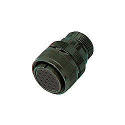
Caution
Product Description
[Features]
• MIL-DTL-5015 (MIL-C-5015) compliant connector.
• Mates with straight plugs or angle plugs, enabling cable extension connections.
• MMS versions do not support key position changes.
[Use]
• Use as a relay connection between equipment.

● MIL-DTL-5015 (MIL-C-5015) compliant connector.
● The mating components of the relay adapter are the straight plug / angle plug.

· The MMS series does not support key position changes.
· Other companies' MS connectors can be fitted, but dimensions and characteristics may vary depending on the manufacturer.
Check components carefully before use.
· Please note that parts can be mated with the waterproof model MS connectors / cable clamps, but this will invalidate their waterproofing.
· The back shell of MMS connectors with shell sizes 14S, 24 and 28 cannot be disassembled. In addition, the insulator material is rubber.
Specifications

| Factory Code | Model Number | Shell | Arrangement | Contact Shape | Number of Cores |
| M | MS3101B | 12S | 3 | P Male (Pin) S Female (Socket) | 2 |
| N | |||||
| M | 14S | 2 | 4 | ||
| N | |||||
| M | 6 | 6 | |||
| N | |||||
| M | 7 | 3 | |||
| N | |||||
| M | 16S | 1 | 7 | ||
| N | |||||
| M | 16 | 10 | 3 | ||
| N | |||||
| M | 18 | 1 | 10 | ||
| N | |||||
| M | 10 | 4 | |||
| M | 11 | 5 | |||
| N | |||||
| M | 20 | 4 | 4 | ||
| N | |||||
| M | 15 | 7 | |||
| N | |||||
| M | 16 | 9 | |||
| N | |||||
| M | 27 | 14 | |||
| N | |||||
| M | 29 | 17 | |||
| N | |||||
| D | MS3101A | 14S | 1 | P Male (Pin) S Female (Socket) | 3 |
| 5 | 5 | ||||
| 9 | 2 | ||||
| 16S | 5 | 3 | |||
| 8 | 5 | ||||
| 18 | 4 | 4 | |||
| 5 | 3 | ||||
| 8 | 8 | ||||
| 10 | 4 | ||||
| 12 | 6 | ||||
| 19 | 10 | ||||
| 20 | 5 | ||||
| 21 | 3 | ||||
| 22 | 3 | ||||
| 20 | 2 | 1 | |||
| 7 | 8 | ||||
| 17 | 6 | ||||
| 18 | 9 | ||||
| 22 | 6 | ||||
| 23 | 2 |
N:JAE
D:DDK
| Factory Code | Model Number | Shell | Arrangement | Contact Shape | Number of Cores |
| M | MS3101B | 22 | 2 | P Male (Pin) S Female (Socket) | 3 |
| N | |||||
| M | 14 | 19 | |||
| N | |||||
| M | 22 | 4 | |||
| N | |||||
| M | 23 | 8 | |||
| N | |||||
| M | 24 | 7 | 16 | ||
| N | |||||
| M | 10 | 7 | |||
| N | |||||
| M | 11 | 9 | |||
| N | |||||
| M | 20 | 11 | |||
| N | |||||
| M | 28 | 24 | |||
| N | |||||
| M | 28 | 6 | 3 | ||
| N | |||||
| M | 11 | 22 | |||
| N | |||||
| M | 12 | 26 | |||
| N | |||||
| M | 20 | 14 | |||
| N | |||||
| M | 21 | 37 | |||
| N | |||||
| N | 32 | 7 | 35 | ||
| M | 36 | 10 | 48 | ||
| N | |||||
| D | MS3101A | 22 | 10 | P Male (Pin) S Female (Socket) | 4 |
| 19 | 14 | ||||
| 28 | 7 | ||||
| 24 | 2 | 7 | |||
| 5 | 16 | ||||
| 22 | 4 | ||||
| 28 | 10 | 7 | |||
| 15 | 35 | ||||
| 16 | 20 | ||||
| 32A | 10 | 54 | |||
| 32 | 1 | 5 | |||
| 2 | 5 | ||||
| 5 | 2 | ||||
| 8 | 30 | ||||
| 9 | 14 | ||||
| 17 | 4 | ||||
| 414 | 52 | ||||
| 36 | 3 | 6 | |||
| 4 | 3 | ||||
| 9 | 31 | ||||
| 73 | 73 |
N:JAE
D:DDK
MIL Standard Compliant MS Connector
Common Specifications
Applicable Wire Size and Contact Size
Appropriate wire coating stripping length is the dimension of the contact solder hole length (L size) plus about 1 ~ 3 mm. Please note that the L dimension and D dimension of the male connector (pin) and the female connector (socket) are the same. When selecting the cable, please check if the cable fits into the inner diameter of the cable clamp.| Contact | Compatible Electric Wire Size | ||||
|---|---|---|---|---|---|
| Contact Size | Solder Hole Diameter φD (mm) | Pin Contact Contacting Part Diameter φA (mm) | L (mm) | AWG | Conductor Section Area mm2 |
| #16 | 1.85 | 1.6 | 6.4 | 16 ~ 20 | 1.25 or less |
| #12 | 2.95 | 2.4 | 9.5 | 12 ~ 14 | 3.5 or less |
| #8 | 5.31 | 3.6 | 12.7 | 8 ~ 10 | 8 or less |
| #4 | 8.45 | 5.7 | 15.9 | 4 ~ 6 | 22 or less |
| #0 | 11.91 | 9.1 | 15.9 | 0 ~ 2 | 50 or less |

Electrical Properties
| Contact Resistance | Contact Size | Test Current DC | Voltage Drop | Couple the male and the female side of the connector the same way as in operating conditions, send test current, measure using the voltage drop method and fulfill the value on the left. |
|---|---|---|---|---|
| #16 | 20 A | 21 mV or lower | ||
| #12 | 35 A | 20 mV or lower | ||
| #8 | 60 A | 12 mV or lower | ||
| #4 | 110 A | 10 mV or lower | ||
| #0 | 200 A | 10 mV or lower |
Mechanical Properties
| Thermal Shock | Low Temperature | High Temperature | Carry out 5 consecutive cycles, with the low temperature and high temperature on the left as 1 cycle. The time exposed to low and high temperature must be 30 minutes or more. | ||||
|---|---|---|---|---|---|---|---|
-55 +0℃ -5℃ | +125 +3℃-0℃ | ||||||
| (1) There should be no cracks or damage in the connector. (2) After completion, the voltage resistance test should be satisfied. | |||||||
| Humidity Resistance | The following voltage resistance should be satisfied. | Expose the coupled connectors and panel mount to temperature 71±2°C and relative humidity 95±3% for 14 days, and then, without drying, perform the voltage resistance test in the left table for 5 minutes. | |||||
| Test Category Symbol | VAC (r.m.s.) | ||||||
| INST | 300 | ||||||
| A | 750 | ||||||
| D | 1,350 | ||||||
| E | 1,875 | ||||||
| B | 2,775 | ||||||
| C | 4,500 | ||||||
| Corrosion | (1) There should be no exposed metal or corrosion damaging the coupling or detachment of the connector. (2) Measurement of Contact Resistance | Expose for 48 hours to salt spray with concentration 5% and temperature 35°C; after that, wash under running water and dry for 12 hours in an air-circulating chamber at temperature of 38±3°C; finally, perform contact resistance and voltage resistance tests. | |||||
| Contact Size | Test Current | Voltage Drop (or Less) | |||||
| #16 | 20 A | 35 mV | |||||
| #12 | 35 | 30 | |||||
| #8 | 60 | 25 | |||||
| #4 | 110 | 20 | |||||
| #0 | 200 | 20 | |||||
| (3) The voltage resistance in the following table should be satisfied. | |||||||
| Test Category Symbol | VAC (r.m.s.) | Category Symbol | VAC (r.m.s.) | ||||
| INST | 400 | E | 2,500 | ||||
| A | 1,000 | B | 3,500 | ||||
| D | 1,800 | C | 6,000 | ||||
Environmental Properties
| Single Contact Insertion and Removal Force | Contact Size | Average | Maximum | Minimum | Insertion and removal force is measured using a randomly extracted male and female. The average force should be at or below the average values shown on the left, and 96% of all values should be at or below the maximum values and at or above the minimum values. |
|---|---|---|---|---|---|
| #16 | 0.95 kg | 1.36 kg | 0.11 kg | ||
| #12 | 1.59 | 2.27 | 0.23 | ||
| #8 | 3.18 | 4.54 | 0.34 | ||
| #4 | 4.76 | 6.8 | 0.45 | ||
| #0 | 6.35 | 9.07 | 0.91 | ||
| Contact Retention Force | Contact Size | Axial Load (kg) | Contact Size | Axial Load (kg) | It should withstand axial load in both directions as shown on the left. |
| #16 | 4.5 | #4 | 9.1 | ||
| #12 | 6.8 | #0 | 11.3 | ||
| #8 | 9.1 | ||||
| Vibration | (1) There should be no current cut-off of 10 μsec or more during the test. (2) After completion, the voltage resistance test should be satisfied. (3) There should be no disconnection of the coupling, cracks, damage or looseness in any part. | Connect the wired connector and the panel mount by the usual method, and perform a vibration test using MIL-STD-1344. During the test, pass 100 mA current through the connector, inspect interruption of the current by a suitable method, and perform a voltage resistance test and visual inspection. | |||
| Impact | (1) After completion, the requirements for contact resistance should be satisfied. (2) There should be no cracks, damage or looseness in any part. | Apply acceleration of 50 G at a 90° angle to each axis direction to the wired and coupled connector and panel mount. | |||
| Service Life | (1) The requirements for contact resistance should be satisfied. (2) There should be no electrical or mechanical abnormalities. | Remove the coupling nut of the connector and insert and remove it 600 times at a speed not exceeding 500 times per 1 hour. | |||
Contact Arrangement Table (by number of cores) View from the male (pin) connector coupling surface.


Arrangement No.
The left side is the shell size of the entire connector. The right side is the arrangement number of the contact. Together these compose the Arrangement Number.
Core Number Composition
The right side is the size of 1 contact. The left side is the number of contacts.
| Arrangement No. | Contact Shape | Contact Composition | Rated Current (A) (Note 1) | Insulation Resistance MΩ (or higher) | Rated Voltage (Note 2) (Note 3) | Test Category Symbol (Note 4) | ||||
|---|---|---|---|---|---|---|---|---|---|---|
| Shell Size | Arrangement Number | Total Number of Cores | Core Number Composition | Contact Size | VDC or less Text shows Contact No. | VAC (r.m.s.) or less Text shows Contact No. Parentheses show voltage resistance / VAC (rms) | ||||
| 10SL | 3 | P Male (Pin) S Female (Socket) | 3 | 3 | #16 | 13 | 5,000 | 700 | 500 (2000) | A |
| 4 | 2 | 2 | ||||||||
| 12S | 3 | 2 | 2 | |||||||
| 14S | 1 | 3 | 3 | |||||||
| 2 | 4 | 4 | 250 | 200 (1000) | INST | |||||
| 5 | 5 | 5 | ||||||||
| 6 | 6 | 6 | ||||||||
| 7 | 3 | 3 | 700 | 500 (2000) | A | |||||
| 9 | 2 | 2 | ||||||||
| 16S | 1 | 7 | 7 | |||||||
| 5 | 3 | 3 | ||||||||
| 8 | 5 | 5 | ||||||||
| 16 | 10 | 3 | 3 | #12 | 23 | |||||
| 18 | 1 | 10 | 10 | #16 | 13 | BCFG-700, Others-250 | BCFG-500 (2000), Others-200 (1000) | A (BCFG) INST (Others) | ||
| 4 | 4 | 4 | 1,250 | 900 (2800) | D | |||||
| 5 | 3 | 2 | #12 | 23 | ||||||
| 1 | #16 | 13 | ||||||||
| 8 | 8 | 1 | #12 | 23 | 700 | 500 (2000) | A | |||
| 7 | #16 | 13 | ||||||||
| 10 | 4 | 4 | #12 | 23 | ||||||
| 11 | 5 | 5 | ||||||||
| 12 | 6 | 6 | #16 | 13 | ||||||
| 19 | 10 | 10 | ||||||||
| 20 | 5 | 5 | ||||||||
| 21 | 3 | 3 | #12 | 23 | ||||||
| 22 | 3 | 3 | #16 | 13 | 1,250 | 900 (2800) | D | |||
| 20 | 2 | 1 | 1 | #0 | 150 | ABHG-1250, CDEF-700 | ABHG-900 (2800), CDEF-500 (2000) | D (ABHG) A (CDEF) | ||
| 4 | 4 | 4 | #12 | 23 | 700 | 500 (2000) | A | |||
| 7 | 8 | 8 | #16 | 13 | ||||||
| 15 | 7 | 7 | #12 | 23 | ||||||
| 16 | 9 | 2 | ||||||||
| 7 | #16 | 13 | ||||||||
| 17 | 6 | 5 | #12 | 23 | ||||||
| 1 | #16 | 13 | ||||||||
| 18 | 9 | 3 | #12 | 23 | ||||||
| 6 | #16 | 13 | ||||||||
| 22 | 6 | 3 | #8 | 46 | ||||||
| 3 | #16 | 13 | ||||||||
| 23 | 2 | 2 | #8 | 46 | ||||||
| 27 | 14 | 14 | #16 | 13 | ||||||
| 29 | 17 | 17 | ||||||||
| 22 | 2 | 3 | 3 | #8 | 46 | 1,250 | 900 (2800) | D | ||
| 10 | 4 | 4 | #16 | 13 | 1,750 | 1250 (3500) | E | |||
| 14 | 19 | 19 | 700 | 500 (2000) | A | |||||
| 19 | 14 | 14 | ||||||||
| 22 | 4 | 4 | #8 | 46 | ||||||
| 23 | 8 | 8 | #12 | 23 | H-1250, Others-700 | H-900 (2800), Others-500 (2000) | D (H) A (Others) | |||
| 28 | 7 | 7 | 700 | 500 (2000) | A | |||||
| 24 | 2 | 7 | 7 | 1,250 | 900 (2800) | D | ||||
| 5 | 16 | 16 | #16 | 13 | 700 | 500 (2000) | A | |||
| 7 | 16 | 2 | #12 | 23 | ||||||
| 14 | #16 | 13 | ||||||||
| 10 | 7 | 7 | #8 | 46 | ||||||
| 11 | 9 | 3 | ||||||||
| 6 | #12 | 23 | ||||||||
| 20 | 11 | 2 | 1,250 | 900 (2800) | D | |||||
| 9 | #16 | 13 | ||||||||
| 22 | 4 | 4 | #8 | 46 | ||||||
| 28 | 24 | 24 | #16 | 13 | 250 | 200 (1000) | INST | |||
| 28 | 6 | P Male (Pin) S Female (Socket) | 3 | 3 | #4 | 80 | 5,000 | 1,250 | 900 (2800) | D |
| 10 | 7 | 2 | G-1250, Others-700 | G-900 (2800), 2 #8 46 Others-500 (2000) | D (G) A (Others) | |||||
| 2 | #8 | 46 | ||||||||
| 3 | #12 | 13 | ||||||||
| 11 | 22 | 4 | 700 | 500 (2000) | A | |||||
| 18 | #16 | 13 | ||||||||
| 12 | 26 | 26 | ||||||||
| 15 | 35 | 35 | ||||||||
| 16 | 20 | 20 | ||||||||
| 20 | 14 | 10 | #12 | 23 | ||||||
| 4 | #16 | 13 | ||||||||
| 21 | 37 | 37 | ||||||||
| 32 | 1 | 5 | 2 | #0 | 150 | A-1750, Others-1250 | A-1250 (3500), Others-900 (2800) | (A) D (Others) | ||
| 3 | #12 | 23 | ||||||||
| 2 | 5 | 3 | #4 | 80 | 1,750 | 1250 (3500) | E | |||
| 2 | #16 | 13 | ||||||||
| 5 | 2 | 2 | #0 | 150 | 1,250 | 900 (2800) | D | |||
| 7 | 35 | 7 | #12 | 23 | ABhj-250, Others-700 | ABhj-200 (1000), Others-500 (2000) | INST (ABhj) A (Others) | |||
| 28 | #16 | 13 | ||||||||
| 8 | 30 | 6 | #12 | 23 | 700 | 500 (2000) | A | |||
| 24 | #16 | 13 | ||||||||
| 9 | 14 | 2 | #4 | 80 | 1,250 | 900 (2800) | D | |||
| 12 | #16 | 13 | ||||||||
| 32 A | 10 | 54 | 54 | 700 | 500 (2000) | A | ||||
| 32 | 17 | 4 | 4 | #4 | 80 | 1,250 | 900 (2800) | D | ||
| 414 | 52 | 52 | #16 | 13 | 700 | 500 (2000) | A | |||
| 36 | 3 | 6 | 3 | #0 | 150 | 1,250 | 900 (2800) | D | ||
| 3 | #12 | 23 | ||||||||
| 4 | 3 | 3 | #0 | 150 | A-1250, BC-700 | A-900 (2800), BC-500 (2000) | D (A) A (BC) | |||
| 5 | 4 | 4 | 700 | 500 (2000) | A | |||||
| 9 | 31 | 1 | #4 | 80 | ||||||
| 2 | #8 | 46 | ||||||||
| 14 | #12 | 23 | ||||||||
| 14 | #16 | 13 | ||||||||
| 10 | 48 | 48 | ||||||||
| 73 | 73 | 73 | ||||||||
| 48 | 5 | 100 | 1 | #8 | 46 | |||||
| 9 | #12 | 23 | ||||||||
| 90 | #16 | 13 | ||||||||
Note 2: Rather than the size of the contact or shell, rated voltage changes by arrangement of contacts.
Note 3: In some items, rated voltage diverges by each contact even when within the same connector.
Note 4: Properties will vary depending on the test category.

About Change in Mis-insertion Prevention Key Position (Angle)

Straight Connector

Outline Drawing

| Shell Size | Coupling Screw A Screw | Size (mm) | |||||
|---|---|---|---|---|---|---|---|
| Cable Entry φB ±0.3 | Effective Screw Length J ±0.3 | Total Length L or less | Outer Diameter Q ±0.8 | Conduit Screw V Screw | Screw Length W or more | ||
| 10SL | 5/8-24UNEF-2B | 9.6 | 13.49 | 34.9 | 22.22 | 5/8-24UNEF-2A | 9.53 |
| 12S | 3/4-20UNEF-2B | 9.6 | 13.5 | 42.8 | 25.4 | 5/8-24UNEF-2A | 9.5 |
| 14S | 7/8-20UNEF-2B | 12.5 | 13.5 | 42.8 | 28.6 | 3/4-20UNEF-2A | 9.5 |
| 16S | 1-20UNEF-2B | 15.6 | 13.5 | 42.8 | 31.8 | 7/8-20UNEF-2A | 9.5 |
| 16 | 1-20UNEF-2B | 15.6 | 18.3 | 52.4 | 31.8 | 7/8-20UNEF-2A | 9.5 |
| 18 | 1-1/8-18UNEF-2B | 20.2 | 18.3 | 52.4 | 34.1 | 1-20UNEF-2A | 9.5 |
| 20 | 1-1/4-18UNEF-2B | 23.0 | 18.3 | 55.6 | 37.3 | 1-3/16-18UNEF-2A | 9.5 |
| 22 | 1-3/8-18UNEF-2B | 23.2 | 18.3 | 55.6 | 40.5 | 1-3/16-18UNEF-2A | 9.5 |
| 24 | 1-1/2-18UNEF-2B | 29.5 | 18.3 | 58.7 | 43.7 | 1-7/16-18UNEF-2A | 9.5 |
| 28 | 1-3/4-18UNS-2B | 29.8 | 18.3 | 58.7 | 50.0 | 1-7/16-18UNEF-2A | 9.5 |
| 32 | 2-18UNS-2B | 37.5 | 18.3 | 61.9 | 56.4 | 1-3/4-18UNS-2A | 11.1 |
| 36 | 2-1/4-16UN-2B | 43.8 | 18.3 | 61.9 | 62.7 | 2-18UNS-2A | 12.7 |
| 48 | 3-16UN-2B | 69.1 | 18.3 | 65.1 | 81.8 | 3-16UN-2A | 15.9 |
Angled Connector

Outline Drawing

| Shell Size | Coupling Screw A Screw | Size (mm) | |||||||
|---|---|---|---|---|---|---|---|---|---|
| Cable Entry B ±0.3 | Effective Screw Length J ±0.3 | Total Length L or less | M ±0.8 | Outer Diameter Q ±0.8 | U ±0.8 | Conduit Screw V Screw | Screw Length W or more | ||
| 12S | 3/4-20UNEF-2B | 9.6 | 13.5 | 50.8 | 41.7 | 25.4 | 25.4 | 5/8-24UNEF-2A | 9.5 |
| 14S | 7/8-20UNEF-2B | 12.5 | 13.5 | 54.0 | 43.3 | 28.6 | 27.0 | 3/4-20UNEF-2A | 9.5 |
| 16S | 1-20UNEF-2B | 15.6 | 13.5 | 60.3 | 48.0 | 31.8 | 28.6 | 7/8-20UNEF-2A | 9.5 |
| 16 | 1-20UNEF-2B | 15.6 | 18.3 | 65.1 | 52.8 | 31.8 | 28.6 | 7/8-20UNEF-2A | 9.5 |
| 18 | 1-1/8-18UNEF-2B | 18.6 | 18.3 | 68.3 | 54.4 | 34.1 | 32.1 | 1-20UNEF-2A | 9.5 |
| 20 | 1-1/4-18UNEF-2B | 23.0 | 18.3 | 77.0 | 60.7 | 37.3 | 33.7 | 1-3/16-18UNEF-2A | 9.5 |
| 22 | 1-3/8-18UNEF-2B | 23.2 | 18.3 | 77.0 | 60.7 | 40.5 | 33.3 | 1-3/16-18UNEF-2A | 9.5 |
| 24 | 1-1/2-18UNEF-2B | 28.0 | 18.3 | 86.5 | 67.1 | 43.7 | 34.9 | 1-7/16-18UNEF-2A | 9.5 |
| 28 | 1-3/4-18UNS-2B | 28.2 | 18.3 | 86.5 | 67.1 | 50.0 | 38.5 | 1-7/16-18UNEF-2A | 9.5 |
| 32, 32A | 2-18UNS-2B | 35.9 | 18.3 | 95.2 | 71.8 | 56.4 | 46.4 | 1-3/4-18UNS-2A | 11.1 |
| 36 | 2-1/4-16UN-2B | 42.2 | 18.3 | 100.0 | 73.4 | 62.7 | 51.2 | 2-18UNS-2A | 12.7 |
| 48 | 3-16UN-2B | 65.9 | 18.3 | 125.4 | 86.5 | 81.8 | 59.1 | 3-16UN-2A | 15.9 |
Relay Connector

Outline Drawing

| Shell Size | Coupling Screw A Screw | Size (mm) | |||||
|---|---|---|---|---|---|---|---|
| Effective Screw Length B or More | Total Length L or less | Length to Flange M +0.4 -0 | Outer Diameter N or Less | Conduit Screw V Screw | Screw Length W or more | ||
| 12S | 3/4-20UNEF-2A | 9.5 | 42.88 | 14.3 | 26.97 | 5/8-24UNEF-2A | 25.4 |
| 14S | 7/8-20UNEF-2A | 9.5 | 42.88 | 14.3 | 29.36 | 3/4-20UNEF-2A | 27.0 |
| 16S | 1-20UNEF-2A | 9.5 | 42.88 | 14.3 | 31.75 | 7/8-20UNEF-2A | 28.6 |
| 16 | 1-20UNEF-2A | 15.9 | 52.37 | 19.0 | 31.75 | 7/8-20UNEF-2A | 28.6 |
| 18 | 1-1/8-18UNEF-2A | 15.9 | 52.37 | 19.0 | 34.14 | 1-20UNEF-2A | 32.1 |
| 20 | 1-1/4-18UNEF-2A | 15.9 | 55.58 | 19.0 | 37.31 | 1-3/16-18UNEF-2A | 33.7 |
| 22 | 1-3/8-18UNEF-2A | 15.9 | 55.58 | 19.0 | 40.49 | 1-3/16-18UNEF-2A | 33.3 |
| 24 | 1-1/2-18UNEF-2A | 15.9 | 58.72 | 19.0 | 43.66 | 1-7/16-18UNEF-2A | 34.9 |
| 28 | 1-3/4-18UNS-2A | 15.9 | 58.72 | 19.0 | 50.01 | 1-7/16-18UNEF-2A | 38.5 |
| 32, 32A | 2-18UNS-2A | 15.9 | 61.93 | 19.0 | 56.36 | 1-3/4UNS-2A | 46.4 |
| 36 | 2-1/4-16UN-2A | 15.9 | 61.93 | 19.0 | 62.71 | 2-18UNS-2A | 51.2 |
| 48 | 3-16UN-2A | 15.9 | 65.07 | 15.9 | 81.76 | 3-16UN-2A | 59.1 |
Panel Mount

Outline Drawing

| Shell Size | A Screw | Size (mm) | |||||||
|---|---|---|---|---|---|---|---|---|---|
| B or more | K or less | L or less | M +0.79-0 | φN +0-4.78 | R ±0.13 | S ±0.79 | φT +0.25-0.13 | ||
| 10SL | 5/8-24UNEF-2A | 9.53 | 2.1 | 21.9 | 14.28 | 15.9 | 18.26 | 25.4 | 3.05 |
| 12S | 3/4-20UNEF-2A | 9.52 | 2.4 | 24.3 | 14.27 | 19.86 | 20.62 | 27.79 | 3.05 |
| 14S | 7/8-20UNEF-2A | 9.52 | 2.4 | 24.3 | 14.27 | 23.01 | 23.01 | 30.18 | 3.05 |
| 16S | 1-20UNEF-2A | 9.52 | 2.4 | 24.3 | 14.27 | 24.61 | 24.61 | 32.54 | 3.05 |
| 16 | 1-20UNEF-2A | 15.88 | 2.4 | 29.1 | 19.05 | 24.61 | 24.61 | 32.54 | 3.05 |
| 18 | 1-1/8-18UNEF-2A | 15.88 | 3.0 | 28.6 | 19.05 | 26.97 | 26.97 | 34.92 | 3.05 |
| 20 | 1-1/4-18UNEF-2A | 15.88 | 3.0 | 29.4 | 19.05 | 29.36 | 29.36 | 38.10 | 3.05 |
| 22 | 1-3/8-18UNEF-2A | 15.88 | 3.0 | 29.4 | 19.05 | 31.75 | 31.75 | 41.28 | 3.05 |
| 24 | 1-1/2-18UNEF-2A | 15.88 | 3.0 | 33.4 | 20.62 | 34.92 | 34.92 | 44.45 | 3.73 |
| 28 | 1-3/4-18UNS-2A | 15.88 | 3.0 | 33.4 | 20.62 | 39.67 | 39.67 | 50.80 | 3.73 |
| 32, 32A | 2-18UNS-2A | 15.88 | 4.3 | 33.4 | 22.22 | 44.45 | 44.45 | 57.15 | 4.39 |
| 36 | 2-1/4-16UN-2A | 15.88 | 4.3 | 33.4 | 22.22 | 49.23 | 49.23 | 63.50 | 4.39 |
| 48 | 3-16UN-2A | 15.88 | 4.3 | 34.2 | 22.22 | 66.68 | 66.68 | 82.55 | 4.39 |

Current Capacity of Entire Connector
| Total Number of Cores | 1 | 2 | 3 | 4 | 5 | 6 | 7 | 8 | 9 | 10 | 11 | 12 | 13 | 14 |
|---|---|---|---|---|---|---|---|---|---|---|---|---|---|---|
| Reduction Factor (%) | 1 | 0.943 | 0.886 | 0.829 | 0.771 | 0.714 | 0.657 | 0.6 | 0.543 | 0.486 | 0.429 | 0.371 | 0.314 | 0.257 |
Rated Current Value per 1 Contact x Number of Cores x Reduction Factor = Allowable Current of Entire Connector
13 A x 2 cores x 0.943 = 24.518 A
(When Arrangement Number is 12S-3)
Therefore, 24.518 A can be used for the entire connector.
(Contact A Rated Current x Contact A Number of Cores + Contact B Rated Current x Contact B Number of Cores) x Reduction Factor (for the total number of cores) = Allowable Current of Entire Connector
(23 A x 2 cores + 13 A x 7 cores) x 0.543 = 74.391 A
(When Arrangement Number is 20-16)
Therefore, 74.391 A can be used for the entire connector.
Rated Current Value x Number of Cores x 20% = Allowable Current of Entire Connector
13 A x 17 cores x 0.2 = 44.2 A
(When Arrangement Number is 20-29)
Therefore, 44.2 A can be used for the entire connector.
(Contact A Rated Current x Contact A Number of Cores + Contact B Rated Current x Contact B Number of Cores) x 20% = Allowable Current of Entire Connector
(23 A x 4 cores + 13 A x 18 cores) x 0.2 = 65.2 A
(When Arrangement Number is 28-11)
Therefore, 65.2 A can be used for the entire connector.
Soldering Method
