(!) Since support from Microsoft will end on January 14 2020, Windows 7 user might not be able to use MISUMI website effectively. Please consider to update your system as ‘MISUMI Website system requirement’.


- inCAD Library Home
- > No.000291 Magazine Transfer Mechanism
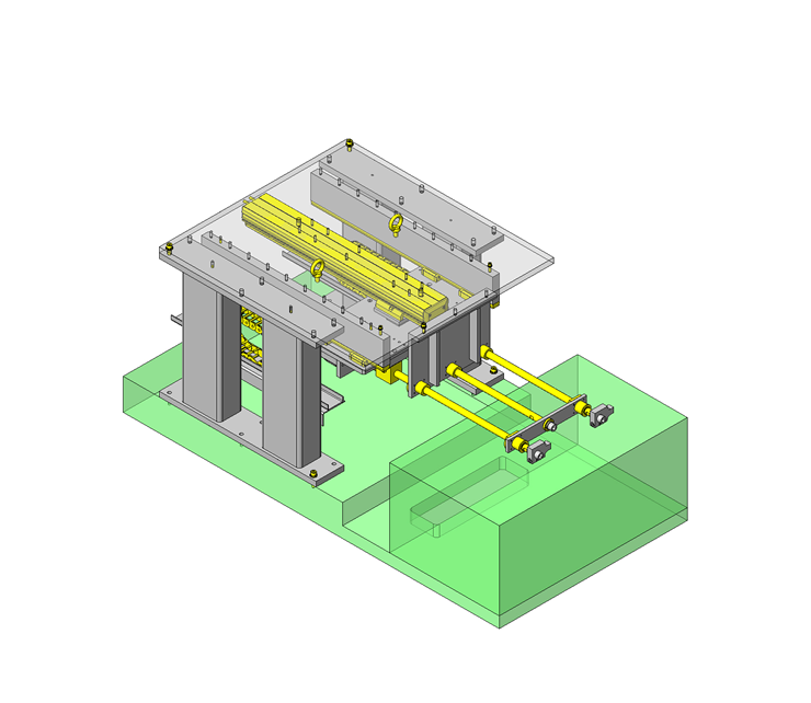
No.000291 Magazine Transfer Mechanism
31
The rotary hand that pulls magazines out of the box.
Relevant category


Single Axis Robot

| Product name | Single Axis Robot RSH1 |
|---|---|
| Part number | RSH106-C22A-C-F0-3-300 |
Selection criteria
Based on stroke, accuracy and thrust force.
Available sizes
■Single Axis Robot RSH1
| Height (mm) | Type | Lead (mm) | Stroke (50mm Increments) |
|---|---|---|---|
| 65 | RSH1 | 6 | 150-800 |
| 12 | |||
| 20 | |||
| RSH2 | 5 | 150-1050 | |
| 10 | |||
| 20 | |||
| 30 | |||
| RSH3 | 5 | 150-1050 | |
| 10 | |||
| 20 |
Selection steps
■Single Axis Robot Selection Steps
Load Capacity
↓
Stroke
↓
Cycle Time or Max. Speed
↓
Check for Details
Accuracy Info.
Single Axis Robot Accuracy
| Height (mm) | Type | Lead (mm) | Stroke (50mm Increments) | Positioning Repeatability (mm) |
|---|---|---|---|---|
| 65 | RSH1 | 6 | 150-800 | ±0.02 |
| 12 | ||||
| 20 | ||||
| RSH2 | 5 | 150-1050 | ±0.01 | |
| 10 | ||||
| 20 | ||||
| 30 | ||||
| RSH3 | 5 | 150-1050 | ±0.01 | |
| 10 | ||||
| 20 |
Performance info.
■Speeds / Loads (Load info.) of Single Axis Robot
| Type | Lead (mm) | Max. Load Capacity (kg) | Allowable Moment (N・m) | Max. Velocity (mm/sec) | ||||||||
|---|---|---|---|---|---|---|---|---|---|---|---|---|
| Horizontal | Vertical | Pitching | Yawing | Rolling | 150- 550st | 600 st | 650 st | 700 st | 750 st | 800 st | ||
| RSH1 | 6 | 40 | 8 | 95 | 70 | 110 | 360 | 324 | 270 | 234 | 216 | 180 |
| 12 | 20 | 4 | 720 | 648 | 540 | 468 | 432 | 360 | ||||
| 20 | 12 | - | 1200 | 1080 | 900 | 780 | 720 | 600 | ||||
| Type | Lead (mm) | Max. Load Capacity (kg) | Allowable Moment (N・m) | Max. Velocity (mm/sec) | |||||||||||
|---|---|---|---|---|---|---|---|---|---|---|---|---|---|---|---|
| Horizontal | Vertical | Pitching | Yawing | Rolling | 150- 650st | 700 st | 750 st | 800 st | 850 st | 900 st | 950 st | 1000 st | 1050 st | ||
| RSH2 | 5 | 50 | 16 | 95 | 70 | 110 | 300 | 255 | 225 | 195 | 180 | 165 | 150 | 135 | 120 |
| 10 | 40 | 8 | 600 | 510 | 450 | 390 | 360 | 330 | 300 | 270 | 240 | ||||
| 20 | 20 | 4 | 1200 | 1020 | 900 | 780 | 720 | 660 | 600 | 540 | 480 | ||||
| 30 | 7 | - | 1800 | 1530 | 1350 | 1170 | 1080 | 990 | 900 | 810 | 720 | ||||
| Type | Lead (mm) | Max. Load Capacity (kg) | Allowable Moment (N・m) | Max. Velocity (mm/sec) | ||||||||||||
|---|---|---|---|---|---|---|---|---|---|---|---|---|---|---|---|---|
| Horizontal | Pitching | Yawing | Rolling | 150- 600st | 650 st | 700 st | 750 st | 800 st | 850 st | 900 st | 950 st | 1000 st | 1050 st | |||
| RSH3 | 5 | 80 | 163 | 128 | 143 | 300 | 255 | 225 | 195 | 180 | 165 | 150 | 135 | 120 | 105 | |
| 10 | 60 | 600 | 510 | 450 | 390 | 360 | 330 | 300 | 270 | 240 | 210 | |||||
| 20 | 30 | 1200 | 1020 | 900 | 780 | 720 | 660 | 600 | 540 | 480 | 420 | |||||
Technical Calculations
■Technical Calculation for Single Axis Robot
Selection Method of Single Axis Robot
https://th.misumi-ec.com/en/maker/misumi/mech/product/rs/

Linear Shafts

| Product name | Precision Hollow Linear Shafts - Straight |
|---|---|
| Part number | PSPTR16-520-M12-SC25 |
Selection criteria
Based on accuracy, stroke and design
Available sizes
■Precision Hollow Linear Shafts - Straight
| Material | Hardness | Surface Treatment |
|---|---|---|
| 52100 Bearing Steel | Induction Hardened 52100 Bearing Steel: 58HRC or More 440C Stainless Steel: 56HRC or More | - |
| 440C Stainless Steel | ||
| 52100 Bearing Steel | Hard Chrome Plating: Plating Hardness HV750 - Plating Thickness 5 µm or more | |
| 52100 Bearing Steel | Low Temp. Black Chrome Plating |
■Sizes and Dimensions
| O.D. | Length in 1 mm Increments | Thread Dia. | |||||||||||||
|---|---|---|---|---|---|---|---|---|---|---|---|---|---|---|---|
| 3 | 4 | 5 | 6 | 8 | 10 | 12 | 16 | 20 | 24 | 30 | Rc1/8 | Rc1/4 | Rc3/8 | ||
| 6 | 20~600 | ○ | - | - | - | - | - | - | - | - | - | - | - | - | - |
| 8 | 20~800 | - | ○ | ○ | - | - | - | - | - | - | - | - | - | - | - |
| 10 | 20~800 | - | - | ○ | ○ | - | - | - | - | - | - | - | - | - | - |
| 12 | 20~1000 | - | - | - | - | ○ | - | - | - | - | - | - | ○ | - | - |
| 13 | 25~1000 | - | - | - | - | - | ○ | - | - | - | - | - | ○ | - | - |
| 16 | 30~1200 | - | - | - | - | - | - | ○ | - | - | - | - | - | ○ | - |
| 20 | 30~1200 | - | - | - | - | - | - | - | ○ | - | - | - | - | - | ○ |
| 25 | 35~1200 | - | - | - | - | - | - | - | - | ○ | - | - | - | - | - |
| 30 | 35~1500 | - | - | - | - | - | - | - | - | ○ | - | - | - | - | - |
| 35 | 35~1500 | - | - | - | - | - | - | - | - | - | ○ | - | - | - | - |
| 40 | 50~1500 | - | - | - | - | - | - | - | - | - | ○ | ○ | - | - | - |
| 50 | 60~1500 | - | - | - | - | - | - | - | - | - | - | ○ | - | - | - |
Accuracy Info.
■Accuracy of the Shafts
| O.D. (mm) | O.D. Tolerance (mm) g6 |
|---|---|
| 6 | -0.004 -0.012 |
| 8 | -0.005 -0.014 |
| 10 | |
| 12 | -0.006 -0.017 |
| 13 | |
| 15 | |
| 16 | |
| 18 | |
| 20 | -0.007 -0.020 |
| 25 | |
| 30 | |
| 35 | -0.009 -0.025 |
| 40 | |
| 50 |

Oil Free Bushing Housing Unit

| Product name | Oil Free Bushing with Housing Units |
|---|---|
| Part number | JFBA16 |
| Features | Suitable for horizontal use. Reduces the time of manufacturing and assembling the housing. |
Selection criteria
Housing unit that supports both linear and rotary motion.
Available sizes
■Oil Free Bushing with Housing Units
| Housing | Bushing | |
|---|---|---|
| Material | Surface Treatment | Material |
| Aluminum Alloy | Clear Anodize | Polyacetal |
■Sizes and Dimensions
| I.D. | Mounting Surface - Shaft Bore Dimension | Width | Height |
|---|---|---|---|
| 6 | 14 | 16 | 22 |
| 8 | 16 | 20 | 26 |
| 10 | 19 | 26 | 32 |
| 12 | 20 | 26 | 34 |
| 16 | 27 | 36 | 49 |
Accuracy Info.
■Accuracy of oil free Bushing
| I.D.(mm) | Tolerance |
|---|---|
| 6 | +0.095 +0.045 |
| 8 | |
| 10 | |
| 12 | +0.120 +0.060 |
| 15 | |
| 16 |


-

-
 TERMS AND CONDITIONS FOR USE OF CAD DATA
-
Your access to the CAD data that MISUMI Corporation (hereinafter referred to as the Company) posts on this site (including 3D CAD data, intermediate 3D CAD data and 2D CAD data; hereinafter referred to as the Data) are of products manufactured and/or sold by the Company (hereinafter referred to as the Products) assumes that you have read and accepted these terms and conditions which govern your use of the Data. If you do not agree to these terms and conditions, you must stop using this website and the Data. You must not use the Data for any unlawful purpose or in any manner inconsistent with these terms and conditions.
- 1. CAD Data
- The Data is prepared for assisting the Company's users in the CAD design process by providing dimensions and other Product information. In order to provide the best speed and stability working within this site, the Product drawings were simplified to reduce the size of the Data. For instance, some of the Products are shown without the oil groove shape, screws or spring shape. Also, please be aware that the tolerance, surface roughness and/or chamfer of the Data may vary from the actual Products.
- 2. Disclaimer on Data
- While the Company has carefully prepared the Data, accuracy of the Data is not guaranteed and is subject to the variances as described above. The Company may also modify, add or delete the Data at any time without prior notice. The Company assumes no liability for any direct, indirect, consequential or special damages that you may claim resulted from your use of the Data or any changes to or deletions of the Data regardless of the reason. The Company provides no warranty as to the quality, accuracy, functionality, safety or reliability of the combination of Products and parts. Example applications and combinations of the Products are provided for illustrative purposes only.
- 3. Copyright
-
Copyrights to the content and the Data belong to the Company or the manufacturers of the Products. The said copyright is protected by the Copyright Act and international treaties. The use (including duplication, modification, uploading, posting, transmission, distribution, licensing, sales and publishing) of the Data except for the purpose to use the Data described above without prior approval of the Company is not allowed. The Data cannot be used for any purposes (including sales promotion) except for designing your machine. If you violate this provision or the laws or regulations, the Company may prohibit you from the use of the Data, the Company’s site and/or take legal action. So long as you comply with these terms and conditions, the Company grants to you a non-exclusive, non-transferable, revocable license to access and use the Data for the sole purpose of assisting you in designing machines that incorporate products.
In case that the CAD data is found to have been to be used for any purpose other than mentioned above or against the related laws, MISUMI may take legal actions, including the one for blocking the involved user from using CAD data and from accessing to the MISUMI site. - 4. Disclaimer of Warranty
- ANY AND ALL CONTENT APPEARING ON THIS WEB SITE IS PROVIDED FOR INFORMATIONAL PURPOSES ONLY. THIS WEB SITE, ITS CONTENT AND ITS LINKS ARE PROVIDED ON AN "AS IS" AND "AS AVAILABLE" BASIS AND ARE USED ONLY AT YOUR SOLE RISK, TO THE FULLEST EXTENT PERMISSIBLE BY LAW. THE COMPANY DISCLAIMS ALL WARRANTIES, EXPRESS OR IMPLIED, OF ANY KIND, REGARDING THIS WEB SITE (INCLUDING ITS CONTENT, HARDWARE, SOFTWARE AND LINKS), INCLUDING AS TO FITNESS FOR A PARTICULAR PURPOSE, MERCHANTABILITY, TITLE, NON INFRINGEMENT, RESULTS, ACCURACY, COMPLETENESS, ACCESSIBILITY, COMPATIBILITY, SECURITY AND FREEDOM FROM COMPUTER VIRUS. THE COMPANY WILL NOT BE LIABLE FOR ANY DAMAGES OR LOSSES, INCLUDING DIRECT, INDIRECT, CONSEQUENTIAL, SPECIAL, INCIDENTAL OR PUNITIVE DAMAGES AND/OR LOST PROFITS, IN CONNECTION WITH USE OF THE INTERNET, THIS WEB SITE, ITS CONTENT OR ITS LINKS
Further, the Company will not be liable to you for any failure or delay by the Company to provide access to the Data or any of its obligations under these terms and conditions where such failure or delay is the direct or indirect result of any circumstances beyond the Company's reasonable control (and the Company's obligations will be suspended for the duration of such circumstances).
CAD Download (Unit Assembly)
CAD Download: File Format
CAD Data Limitations
-
Assembly data shows the assembly drawings in the concept design phase. The sole purpose of the data is to explain the structure and functionality of the assembly and is not considered nor to be used as a final design.
You will need to edit the Data so that it meets your specific design conditions. -
Unit assembly Data consists of some sub-assemblies.
It is configured so that each sub-assembly unit can be used as it is or edited. - The Data for fabricated parts is based on easy-to-edit dimensions and shapes in sketches and histories.
- The Data including the third-part components are made by the Company.
* The part in the frame is a sub-assembly unit.
-
Your access to the CAD data that MISUMI Corporation (hereinafter referred to as the Company) posts on this site (including 3D CAD data, intermediate 3D CAD data and 2D CAD data; hereinafter referred to as the Data) are of products manufactured and/or sold by the Company (hereinafter referred to as the Products) assumes that you have read and accepted these terms and conditions which govern your use of the Data. If you do not agree to these terms and conditions, you must stop using this website and the Data. You must not use the Data for any unlawful purpose or in any manner inconsistent with these terms and conditions.
-

- * Unit assembly Data consists of some sub-assemblies.
It is configured so that each sub-assembly unit can be used as it is or edited.
Application Overview
Purpose
- A mechanism used to remove magazines from a box and transfer them to cutting operation.
- The magazine box has limited access. The removal fingers are inserted in the horizontal position between the magazines and the box. Once they are in position, the fingers are rotated to the vertical position so they can engage the magazines.
- Only one layer of magazine is pulled-out during one cycle.
Points for use
- The box used for transporting the magazines is only open on one side.
Target workpiece
- Small-part magazine
- External dimensions: W 280 x D 70 x H 23 mm
- Capacity: 0.22kg (including transporting parts: 0.33 kg)
Design Specifications
Operating Conditions or Design Requirements
- External dimensions: W 600 x D 1005 x H 416 mm
- Pull-out stroke: 257 mm
Required Performance
- Movable object weight: 12 kg
Workpiece weight: 0.33 x 3 = 0.99 kg
12+0.99=12.99kg
Selection criteria for Main Components
- Single axis robot
- Select one with a thrust of 127.3 N (12.99 kg) or more.
Design Evaluation
Verification of main components
- Verify that robot thrust exceeds required thrust.
- Single axis robot
- Thrust: 283 N (catalogue value)
- Required thrust: 12.99 (workpiece Capacity)×9.8=127.3 N<283 N
Other Design Consideration
- To reduce the weight of the arms entering the box, hollow shafts are used.
- Three arms are used in the mechanism that removes the magazines. One is fixed and two are adjustable.
Explore Similar Application Examples

-

-

-

-

-

-

-

-

-

-

-

-

-

-

-

-

-

-

-

-

-

Relevant category
-

-

-

-

-

-

-

-

-

-

-

-

-

-

-

-

-

-

-

-

-

-

-

-

-

-

-

-

-

-

-

-

-

-

-

-

-

-

-

Relevant category
-

-

-

-

-

-

-

-

-

-

-

-

-

-

-

-

-

-

-

-

-

-

-

-

-

-

-

-

-

-

-

-

-

-

-

-

-

-

-

-

-

-

-

-

-

-

-

-

-

-

-

-

-

-

-

-

-

-

-

-

-

-

-

-

-

-


Payment Methods
- Credit Card
-
- Bank
-
- Prompt Pay
-


Social Media
MISUMI Contact
Copyright © MISUMI Corporation All Rights Reserved.