(!) Since support from Microsoft will end on January 14 2020, Windows 7 user might not be able to use MISUMI website effectively. Please consider to update your system as ‘MISUMI Website system requirement’.


- inCAD Library Home
- > No.000163 Simplified Indexing Table
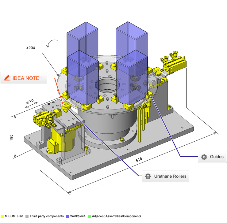
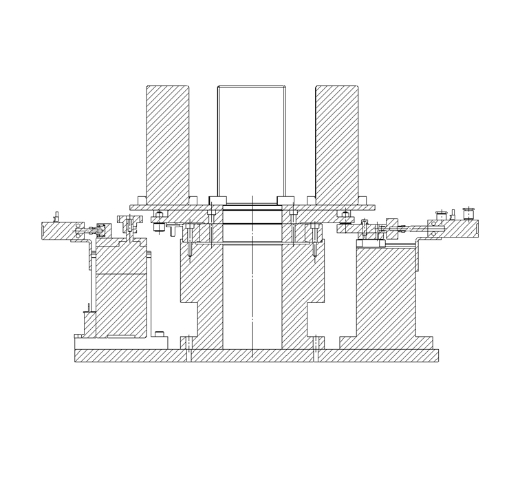
No.000163 Simplified Indexing Table
35
35
Cost effective indexing table.
Relevant category


Urethane Rollers
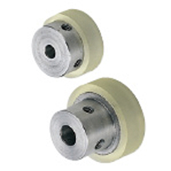
| Product name | Urethane Rollers - Set Screw Holes |
|---|---|
| Part number | UMHS30-8 |
* Orange colored cells in the table below indicate the part numbers used in this example.
Selection criteria
Select a roller with hardened urethane to transmit the drive force of the motor to the turntable.
Available sizes
■Urethane Rollers - Set Screw Type
| Core material | Lining | Hardness |
|---|---|---|
| 304 Stainless Steel | Urethane | Shore A90 |
| Shore A70 | ||
| Shore A50 | ||
| 5052 Aluminum Alloy | Shore A90 | |
| Shore A70 | ||
| Shore A50 |
■Sizes and Dimensions
| O.D. | I.D. |
|---|---|
| φ15 | φ4 |
| φ5 | |
| φ20 | φ4 |
| φ5 | |
| φ25 | φ6 |
| φ8 | |
| φ30 | φ6 |
| φ8 | |
| φ35 | φ8 |
| φ10 | |
| φ40 | φ8 |
| φ10 | |
| φ50 | φ10 |
| φ12 |

Guides

| Product name | Guides- L-Shaped |
|---|---|
| Part number | WGLNC-20-10-10 |
* Orange colored cells in the table below indicate the part numbers used in this example.
Selection criteria
Suitable as a guide for square workpieces
Available sizes
■Workpiece guide (L shaped Standard type)
| Material | Hardness | Surface Treatment |
|---|---|---|
| 1045 Carbon Steel | ― | Black Oxide |
| Electroless Nickel Plating | ||
| 40HRC- | Black Oxide | |
| Electroless Nickel Plating | ||
| 2017 Aluminum Alloy | ― | ― |
| 304 Stainless Steel | ||
| Polyacetal | ||
| MC Nylon | ||
| Conductive MC Nylon R2 | ||
| Tetrafluoroethylene |
■Sizes and Dimensions
| One side (mm) | Height (1 mm Increments) | Installation Hole Dia. (mm) |
|---|---|---|
| 20-50(Increments of 10) | 10-30 | 3.5 |
| 20-50(Increments of 10) | 4.5 | |
| 30-60(Increments of 10) | 5.5 | |
| 30-60(Increments of 10) | 15-30 | 6.5 |
| 40-60(Increments of 10) | 9 |
Accuracy Info
■Accuracy of workpiece guide
Perpendicularity: 0.05

IDEA NOTE Separation of drive source
During maintenance the indexing table is disengaged.

-

-
 TERMS AND CONDITIONS FOR USE OF CAD DATA
-
Your access to the CAD data that MISUMI Corporation (hereinafter referred to as the Company) posts on this site (including 3D CAD data, intermediate 3D CAD data and 2D CAD data; hereinafter referred to as the Data) are of products manufactured and/or sold by the Company (hereinafter referred to as the Products) assumes that you have read and accepted these terms and conditions which govern your use of the Data. If you do not agree to these terms and conditions, you must stop using this website and the Data. You must not use the Data for any unlawful purpose or in any manner inconsistent with these terms and conditions.
- 1. CAD Data
- The Data is prepared for assisting the Company's users in the CAD design process by providing dimensions and other Product information. In order to provide the best speed and stability working within this site, the Product drawings were simplified to reduce the size of the Data. For instance, some of the Products are shown without the oil groove shape, screws or spring shape. Also, please be aware that the tolerance, surface roughness and/or chamfer of the Data may vary from the actual Products.
- 2. Disclaimer on Data
- While the Company has carefully prepared the Data, accuracy of the Data is not guaranteed and is subject to the variances as described above. The Company may also modify, add or delete the Data at any time without prior notice. The Company assumes no liability for any direct, indirect, consequential or special damages that you may claim resulted from your use of the Data or any changes to or deletions of the Data regardless of the reason. The Company provides no warranty as to the quality, accuracy, functionality, safety or reliability of the combination of Products and parts. Example applications and combinations of the Products are provided for illustrative purposes only.
- 3. Copyright
-
Copyrights to the content and the Data belong to the Company or the manufacturers of the Products. The said copyright is protected by the Copyright Act and international treaties. The use (including duplication, modification, uploading, posting, transmission, distribution, licensing, sales and publishing) of the Data except for the purpose to use the Data described above without prior approval of the Company is not allowed. The Data cannot be used for any purposes (including sales promotion) except for designing your machine. If you violate this provision or the laws or regulations, the Company may prohibit you from the use of the Data, the Company’s site and/or take legal action. So long as you comply with these terms and conditions, the Company grants to you a non-exclusive, non-transferable, revocable license to access and use the Data for the sole purpose of assisting you in designing machines that incorporate products.
In case that the CAD data is found to have been to be used for any purpose other than mentioned above or against the related laws, MISUMI may take legal actions, including the one for blocking the involved user from using CAD data and from accessing to the MISUMI site. - 4. Disclaimer of Warranty
- ANY AND ALL CONTENT APPEARING ON THIS WEB SITE IS PROVIDED FOR INFORMATIONAL PURPOSES ONLY. THIS WEB SITE, ITS CONTENT AND ITS LINKS ARE PROVIDED ON AN "AS IS" AND "AS AVAILABLE" BASIS AND ARE USED ONLY AT YOUR SOLE RISK, TO THE FULLEST EXTENT PERMISSIBLE BY LAW. THE COMPANY DISCLAIMS ALL WARRANTIES, EXPRESS OR IMPLIED, OF ANY KIND, REGARDING THIS WEB SITE (INCLUDING ITS CONTENT, HARDWARE, SOFTWARE AND LINKS), INCLUDING AS TO FITNESS FOR A PARTICULAR PURPOSE, MERCHANTABILITY, TITLE, NON INFRINGEMENT, RESULTS, ACCURACY, COMPLETENESS, ACCESSIBILITY, COMPATIBILITY, SECURITY AND FREEDOM FROM COMPUTER VIRUS. THE COMPANY WILL NOT BE LIABLE FOR ANY DAMAGES OR LOSSES, INCLUDING DIRECT, INDIRECT, CONSEQUENTIAL, SPECIAL, INCIDENTAL OR PUNITIVE DAMAGES AND/OR LOST PROFITS, IN CONNECTION WITH USE OF THE INTERNET, THIS WEB SITE, ITS CONTENT OR ITS LINKS
Further, the Company will not be liable to you for any failure or delay by the Company to provide access to the Data or any of its obligations under these terms and conditions where such failure or delay is the direct or indirect result of any circumstances beyond the Company's reasonable control (and the Company's obligations will be suspended for the duration of such circumstances).
CAD Download (Unit Assembly)
CAD Download: File Format
CAD Data Limitations
-
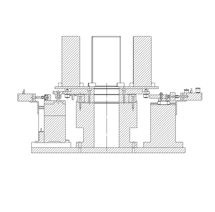
Assembly data shows the assembly drawings in the concept design phase. The sole purpose of the data is to explain the structure and functionality of the assembly and is not considered nor to be used as a final design.
You will need to edit the Data so that it meets your specific design conditions. -
Unit assembly Data consists of some sub-assemblies.
It is configured so that each sub-assembly unit can be used as it is or edited. - The Data for fabricated parts is based on easy-to-edit dimensions and shapes in sketches and histories.
- The Data including the third-part components are made by the Company.
* The part in the frame is a sub-assembly unit.
-
Your access to the CAD data that MISUMI Corporation (hereinafter referred to as the Company) posts on this site (including 3D CAD data, intermediate 3D CAD data and 2D CAD data; hereinafter referred to as the Data) are of products manufactured and/or sold by the Company (hereinafter referred to as the Products) assumes that you have read and accepted these terms and conditions which govern your use of the Data. If you do not agree to these terms and conditions, you must stop using this website and the Data. You must not use the Data for any unlawful purpose or in any manner inconsistent with these terms and conditions.
-

- * Unit assembly Data consists of some sub-assemblies.
It is configured so that each sub-assembly unit can be used as it is or edited.
Application Overview
Purpose
- Purpose
- Indexing table used in magazine transfer.
- Operation
- A geared motor drives a urethane roller which turns the indexing table. A deceleration sensor is used in conjunction with a stop sensor to slowly bring the table to a stop. A wedge is used to physically top the rotation of the table.
Points for use
- Disengage the indexing table during maintenance.
The indexing table is operated slowly.
Target workpiece
- Shape: Magazine
- Size: W80xD50xH140mm
- Weight: 1.5kg
Design Specifications
Operating Conditions or Design Requirements
- Index table outer diameter: φ290mm
- 4 positions
- Cycle time: 1 second for 1 position
- Outer dimensions: W516xD290xH195mm
Required Performance
- Positioning accuracy: ±0.5mm
- Load weight: 1.5×4=6kg
Selection Criteria for Main Components
- Variable geared motor
- As the index table cycle time t is 1 second per position, it takes 4 seconds to rotate one revolution. Therefore, the table rotation speed Nt is 15 rpm.
- As the outer diameter D1 of the part driven by the urethane roller of the geared motor is φ240 and the diameter D2 of the urethane roller of the geared motor is φ30, the rotation speed N of the geared motor is D1/D2 x Nt = 240/30 x 15 = 120rpm.
- A variable geared motor with a variable range of 90 to 1200rpm and a gear head with a reduction ratio i of 1/3 are selected, and the range of variable rotation speed after deceleration should be set to 30 to 400.
Design Evaluation
Verification of main components
- Need to ensure the geared motor allowable torque satisfies the necessary load torque.
- Confirmation of load torque of geared motor
- Conditional value: index table rotation speed: Nt = 15 rpm, outer diameter of table driven part: D1 = φ240mm, diameter of the urethane roller of geared motor: D2 = φ30mm, cycle time: t = 1sec, moment of inertia of rotating part including workpiece: J = 0.083kg・m2
- Rotation speed of geared motor: N = D1/D2 x Nt = 240/30 x 15 = 120rpm
- Load torque of geared motor: T = J/(9.55 x 104) x N/t = 0.083/(9.55 x 104) x 120/1 = 1.04 x 10??N・m
- Allowable torque of geared motor when gear head is mounted (when reduction ratio i = 1/3): Tmax = 0.06N・m
⇒Load torque: T = 1.04 x 10??N・m
< allowable torque: Tmax = 0.06N・m Therefore, the load torque of geared motor is within the allowable range.
- Confirmation of gear head overhang load
- As the allowable overhang load of the gear head used in this device is 98N at the output shaft center, the allowable overhang load of this device is 98N x 16mm/32mm = 49N.
⇒φAs the theoretical thrust of φ16 cylinder on the push side is 40N when the operating pressure is 0.2MPa, the cylinder that presses against motor is used at 0.2MPa.
- As the allowable overhang load of the gear head used in this device is 98N at the output shaft center, the allowable overhang load of this device is 98N x 16mm/32mm = 49N.
Other Design Consideration
- Micro photo sensor is used as a confirmation and deceleration sensor.
Explore Similar Application Examples
Page
-
/
-

-

-

-

-

-

-

-

-

-

-

-

-

-

-

-

-

-

-

-

Relevant category
-

-

-

-

-

-

-

-

-

-

-

-

-

-

-

-

-

-

-

-

-

-

-

-

-

-

-

-

-

-

-

-

-

-

-

-

-

-

Relevant category
-

-

-

-

-

-

-

-

-

-

-

-

-

-

-

-

-

-

-

-

-

-

-

-

-

-

-

-

-

-

-

-

-

-

-

-

-

-

-

-

-

-

-

-

-

-

-

-

-

-

-

-

-

-

-

-

-

-

-

-

-

-

-

-

-

-


Payment Methods
- Credit Card
-
- Bank
-
- Prompt Pay
-


Social Media
MISUMI Contact
Copyright © MISUMI Corporation All Rights Reserved.