(!) Since support from Microsoft will end on January 14 2020, Windows 7 user might not be able to use MISUMI website effectively. Please consider to update your system as ‘MISUMI Website system requirement’.


- inCAD Library Home
- > No.000128 Sorting Mechanism
No.000128 Sorting Mechanism
35
Reduce cycle time by utilizing right/left sorting mechanism
Relevant category


Single axis robot
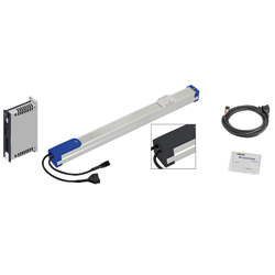
| Product name | Single Axis Robot RS2 |
|---|---|
| Part number | RS220-C1-C-3-150 |
Selection criteria
Robot is selected to minimize jerk during transporting.
Available sizes
■Single axis robot (RS, slider type, No brake)
General specifications
| Ball screw | Motor | Position detector | Operating environment temp - Humidity | Controller input power supply |
|---|---|---|---|---|
| φ8 (C10 Rolled) | Stepping | Resolver (Incremental) | 0〜40℃・35〜85%RH (No condensation) | DC24V±10% |
| φ12 (C10 Rolled) |
Basic specifications
| Slider Upper Surface Height (mm) | Type | Lead (mm) | Stroke (mm) |
|---|---|---|---|
| 51 | RS1 | 2 | 50〜400 (Increment of 50) |
| 6 | |||
| 12 | |||
| 57 | RS2 | 6 | 50〜800 (Increment of 50) |
| 12 | |||
| 20 | |||
| 60 | RS3 | 6 | 50〜800 (Increment of 50) |
| 12 | |||
| 20 |
Selection steps
■Single axis robot selection steps
Load capacity
↓
Stroke
↓
Cycle time or Max. Speed
↓
Detail confirmation
Accuracy Info
Single axis robot accuracy
Repeatability: ±0.02
Performance info.
■Single axis robot Performance info.
| Slider Upper Surface Height (mm) | Type | Lead (mm) | Load capacity(kg) | Max. push force | Allowable moment capacity (N·m) | Max speed (mm/sec) | Rated life | |||
|---|---|---|---|---|---|---|---|---|---|---|
| Horizontal | Vertical | (N) | Pitching | Yawing | Rolling | |||||
| 51 | RS1 | 2 | 6 | 4 | 150 | 19 | 16 | 17 | 100 | 10,000km or more |
| 6 | 4 | 2 | 90 | 300 | ||||||
| 12 | 2 | 1 | 45 | 600 | ||||||
| 57 | RS2 | 6 | 10 | 2 | 90 | 33 | 25 | 30 | 300~190 | 10,000km or more |
| 12 | 6 | 1 | 45 | 600~380 | ||||||
| 20 | 4 | - | 27 | 1000~633 | ||||||
| 60 | RS3 | 6 | 12 | 4 | 120 | 38 | 32 | 34 | 300~190 | 10,000km or more |
| 12 | 8 | 2 | 60 | 600~380 | ||||||
| 20 | 6 | - | 36 | 1000~633 | ||||||
Technical calculations
Convenient sizing software is available to use.

Air gripper
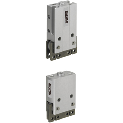
| Product name | Air Gripper - Parallel Type - |
|---|---|
| Part number | ACHK6-N |
| Features | Compact Type Pneumatic Grippers with high precision, high rigidity, strong retaining force and. |
Selection criteria
Compact suitable for workpiece gripping.
Available sizes
■Small parallel air gripper (Integrated sensor)
| Part name | Material | Surface treatment |
|---|---|---|
| Main body | 5056 Aluminum Alloy | Clear anodize |
| Fingers · Attachment mount | 1045 Carbon Steel | Nitriding treatment |
■Specifications and Dimensions
| Operating method | Stroke | Cylinder I.D. | Overall width | Overall height | Thickness |
|---|---|---|---|---|---|
| Single Acting · Double Acting | 4 | φ8 | 26 | 40.5 | 10 |
| 6 | φ12 | 30 | 45 | 16.4 |
Selection steps
■Small parallel gripper selection steps
- Confirmation of Conditions
- (Confirming required stroke,weight, and shape)
↓
- Calculation of required gripping force
-
- 10~20 times of the workpiece weight required
- (Varies by friction coefficient of fingers and workpiece.)
↓
- Model Selection
-
- ●Gripping method (O.D. gripping · I.D. gripping)
- ●Open/close operation method (Single acting or Dual acting)
- ●Stroke
- ●Gripping points and gripping force
Performance info.
■Small parallel gripper (Integrated sensor) load info.
| Stroke | Cylinder I.D. | Operating pressure range | Effective gripping force(N) | Allowable static load(N) | ||
|---|---|---|---|---|---|---|
| Single acting (Spring) | Dual acting | F1 | F2 | |||
| 4 | φ8 | 0.3~0.5MPa | 4.2(1) | 4.9 | 5 | 2.5 |
| 6 | φ12 | 10.4(1.9) | 12.2 | 10 | 5 | |

Cable carrier

| Product name | Cable Carriers Flap Open-Close Type |
|---|---|
| Part number | MHPUS202-45-12-A |
Selection criteria
To protect connection cables
Available sizes
■Cable carrier, Flap open/close type
| Main body | Mounting bracket | |
|---|---|---|
| Material | Material | Surface treatment |
| Nylon 6 + Glass Fiber 20% (Operating temp. -10~80℃) Flammability standards UL94-HB equivalent | Low Carbon Steel | Trivalent chromate |
■Sizes and Dimensions
| Name No. | Bend radius | Number of links | Mounting direction | Inner height | Mounting height | (Required space height) | |||||
|---|---|---|---|---|---|---|---|---|---|---|---|
| Inner height | Height | Inner width | Width | Link pitch | |||||||
| 102 | 19 | 5〜23 | Mounting Direction S For Both Moving and Fixed Ends: Common to the outer and inner circumferences | 9 | 12 | 20 | 27 | 20 | 50 | 65 | |
| 202 | 25 | 6〜34 | Mounting Direction A For Moving Ends: Mounting on the Outer Circumference For Fixed Ends: Common to the Outer and Inner Circumference | Mounting Direction B For Moving Ends: Mounting on the Inner Circumference For Fixed Ends: Common to the Outer and Inner Circumference | 14 | 20 | 14 | 26 | 25 | 70 | 85 |
| 30 | 6〜34 | 80 | 95 | ||||||||
| 45 | 8〜36 | 110 | 125 | ||||||||
| 203 | 30 | 6〜34 | 14 | 20 | 20 | 32 | 25 | 80 | 95 | ||
| 45 | 8〜36 | 110 | 125 | ||||||||
| 204 | 38 | 6〜36 | 14 | 22 | 20 | 40 | 32 | 98 | 118 | ||
| 50 | 7〜37 | 122 | 142 | ||||||||
| 206 | 38 | 6〜36 | 14 | 22 | 40 | 60 | 32 | 98 | 118 | ||
| 50 | 7〜37 | 122 | 142 | ||||||||
| 306 | 50 | 6〜38 | Mounting Direction A For Moving Ends: Common to the Outer and Inner Circumference For Fixed Ends: Mounting on the Outer Circumference | Mounting Direction B For Moving Ends: Common to the Outer and Inner Circumference For Fixed Ends: Mounting on the Inner Circumference | 24 | 34 | 44 | 60 | 45 | 134 | 160 |
| 100 | 10〜42 | 234 | 260 | ||||||||
| 408 | 50 | 6〜38 | 24.5 | 40 | 58 | 78 | 45 | 140 | 170 | ||
| 75 | 8〜40 | 190 | 220 | ||||||||
| 100 | 10〜42 | 240 | 270 | ||||||||
| 150 | 13〜45 | 340 | 370 | ||||||||
| 412 | 50 | 6〜38 | 24.5 | 40 | 97 | 117 | 45 | 140 | 170 | ||
| 75 | 9〜41 | 190 | 220 | ||||||||
| 100 | 10〜42 | 240 | 270 | ||||||||


-
 TERMS AND CONDITIONS FOR USE OF CAD DATA
-
Your access to the CAD data that MISUMI Corporation (hereinafter referred to as the Company) posts on this site (including 3D CAD data, intermediate 3D CAD data and 2D CAD data; hereinafter referred to as the Data) are of products manufactured and/or sold by the Company (hereinafter referred to as the Products) assumes that you have read and accepted these terms and conditions which govern your use of the Data. If you do not agree to these terms and conditions, you must stop using this website and the Data. You must not use the Data for any unlawful purpose or in any manner inconsistent with these terms and conditions.
- 1. CAD Data
- The Data is prepared for assisting the Company's users in the CAD design process by providing dimensions and other Product information. In order to provide the best speed and stability working within this site, the Product drawings were simplified to reduce the size of the Data. For instance, some of the Products are shown without the oil groove shape, screws or spring shape. Also, please be aware that the tolerance, surface roughness and/or chamfer of the Data may vary from the actual Products.
- 2. Disclaimer on Data
- While the Company has carefully prepared the Data, accuracy of the Data is not guaranteed and is subject to the variances as described above. The Company may also modify, add or delete the Data at any time without prior notice. The Company assumes no liability for any direct, indirect, consequential or special damages that you may claim resulted from your use of the Data or any changes to or deletions of the Data regardless of the reason. The Company provides no warranty as to the quality, accuracy, functionality, safety or reliability of the combination of Products and parts. Example applications and combinations of the Products are provided for illustrative purposes only.
- 3. Copyright
-
Copyrights to the content and the Data belong to the Company or the manufacturers of the Products. The said copyright is protected by the Copyright Act and international treaties. The use (including duplication, modification, uploading, posting, transmission, distribution, licensing, sales and publishing) of the Data except for the purpose to use the Data described above without prior approval of the Company is not allowed. The Data cannot be used for any purposes (including sales promotion) except for designing your machine. If you violate this provision or the laws or regulations, the Company may prohibit you from the use of the Data, the Company’s site and/or take legal action. So long as you comply with these terms and conditions, the Company grants to you a non-exclusive, non-transferable, revocable license to access and use the Data for the sole purpose of assisting you in designing machines that incorporate products.
In case that the CAD data is found to have been to be used for any purpose other than mentioned above or against the related laws, MISUMI may take legal actions, including the one for blocking the involved user from using CAD data and from accessing to the MISUMI site. - 4. Disclaimer of Warranty
- ANY AND ALL CONTENT APPEARING ON THIS WEB SITE IS PROVIDED FOR INFORMATIONAL PURPOSES ONLY. THIS WEB SITE, ITS CONTENT AND ITS LINKS ARE PROVIDED ON AN "AS IS" AND "AS AVAILABLE" BASIS AND ARE USED ONLY AT YOUR SOLE RISK, TO THE FULLEST EXTENT PERMISSIBLE BY LAW. THE COMPANY DISCLAIMS ALL WARRANTIES, EXPRESS OR IMPLIED, OF ANY KIND, REGARDING THIS WEB SITE (INCLUDING ITS CONTENT, HARDWARE, SOFTWARE AND LINKS), INCLUDING AS TO FITNESS FOR A PARTICULAR PURPOSE, MERCHANTABILITY, TITLE, NON INFRINGEMENT, RESULTS, ACCURACY, COMPLETENESS, ACCESSIBILITY, COMPATIBILITY, SECURITY AND FREEDOM FROM COMPUTER VIRUS. THE COMPANY WILL NOT BE LIABLE FOR ANY DAMAGES OR LOSSES, INCLUDING DIRECT, INDIRECT, CONSEQUENTIAL, SPECIAL, INCIDENTAL OR PUNITIVE DAMAGES AND/OR LOST PROFITS, IN CONNECTION WITH USE OF THE INTERNET, THIS WEB SITE, ITS CONTENT OR ITS LINKS
Further, the Company will not be liable to you for any failure or delay by the Company to provide access to the Data or any of its obligations under these terms and conditions where such failure or delay is the direct or indirect result of any circumstances beyond the Company's reasonable control (and the Company's obligations will be suspended for the duration of such circumstances).
CAD Download (Unit Assembly)
CAD Download: File Format
CAD Data Limitations
-
Assembly data shows the assembly drawings in the concept design phase. The sole purpose of the data is to explain the structure and functionality of the assembly and is not considered nor to be used as a final design.
You will need to edit the Data so that it meets your specific design conditions. -
Unit assembly Data consists of some sub-assemblies.
It is configured so that each sub-assembly unit can be used as it is or edited. - The Data for fabricated parts is based on easy-to-edit dimensions and shapes in sketches and histories.
- The Data including the third-part components are made by the Company.
* The part in the frame is a sub-assembly unit.
-
Your access to the CAD data that MISUMI Corporation (hereinafter referred to as the Company) posts on this site (including 3D CAD data, intermediate 3D CAD data and 2D CAD data; hereinafter referred to as the Data) are of products manufactured and/or sold by the Company (hereinafter referred to as the Products) assumes that you have read and accepted these terms and conditions which govern your use of the Data. If you do not agree to these terms and conditions, you must stop using this website and the Data. You must not use the Data for any unlawful purpose or in any manner inconsistent with these terms and conditions.
-

- * Unit assembly Data consists of some sub-assemblies.
It is configured so that each sub-assembly unit can be used as it is or edited.
Application Overview
Purpose
- Workpieces discharged from a feeder are sorted to the right or the left by a single axis robot.
- Components are transported by using an air gripper.
Points for use
- Automated mechanism with air grippers and single axis robots.
Target workpiece
- Plastic caps
External dims.: φ20 x L36
Workpiece weight 6.5g
Design Specifications
Operating Conditions or Design Requirements
- External dimensions: W690 x D428 x H427
- Single axis robot stroke: 140mm (Workpiece receiving section)-Max operating stroke: 150mm
- Single axis robot stroke: 115mm (Workpiece Sorting section)-Max operating stroke: 150mm
- Cylinder with twin guides stroke: 10 mm
Selection Criteria for Main Components
- Single axis robot
- Select a robot with a load capacity that exceeds the combined weight of all the moving mechanisms. This actuator should also satisfy the required allowable moment load rating.
- Air gripper
- The allowable static load rating of the gripper should exceed the load weight.
- Cylinder with guides
- Select a cylinder with a load rating that is smaller than the allowable eccentric load (from catalog).
Design Evaluation
Verification of main components
- Verify that the motor has the required load capacity to transport the components in both directions. Ensure that the motor has the required allowable moment rating.
- Single axis robot transported load
- <Right/left air gripper>: 0.253kg
Air gripper: 37g, Speed controller: 8g x 2, Gripper fingers: 8g x 2, Upper drive base: 87g, Upper carrier bracket; 90g, Workpiece: 6.5g - Workpiece sorting mechanism: 1.144kg
Workpiece retainer plate: 680g, Lower drive base: 388g, Workpiece guide: 27g x 2pcs., Fiber unit: 5g x 2pcs., Workpiece: 6.5g x 2pcs. - Robot load capacity: 4kg > Total mass (0.253 + 1.144 = 1.397kg): OK
- <Right/left air gripper>: 0.253kg
Other Design Consideration
- The brackets mounted on the cylinder functions as a location guide for sorting and transporting components.
Explore Similar Application Examples

-

-

-

-

-

-

-

-

-

-

-

-

-

-

-

-

-

-

-

Relevant category
-

-

-

-

-

-

-

-

-

-

-

-

-

-

-

-

-

-

-

-

-

-

-

-

-

-

-

-

-

-

-

-

-

-

-

-

-

-

Relevant category
-

-

-

-

-

-

-

-

-

-

-

-

-

-

-

-

-

-

-

-

-

-

-

-

-

-

-

-

-

-

-

-

-

-

-

-

-

-

-

-

-

-

-

-

-

-

-

-

-

-

-

-

-

-

-

-

-

-

-

-

-

-

-

-

-

-

-


Payment Methods
- Credit Card
-
- Bank
-
- Prompt Pay
-


Social Media
MISUMI Contact
Copyright © MISUMI Corporation All Rights Reserved.