(!) Since support from Microsoft will end on January 14 2020, Windows 7 user might not be able to use MISUMI website effectively. Please consider to update your system as ‘MISUMI Website system requirement’.


- inCAD Library Home
- > No.000080 Feeding Mechanism for Round Bars
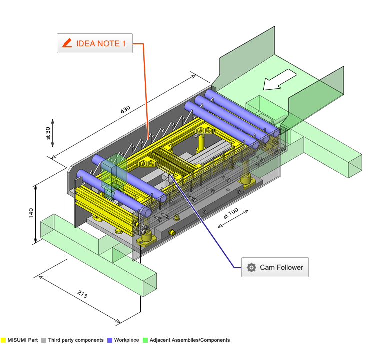
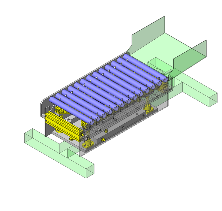
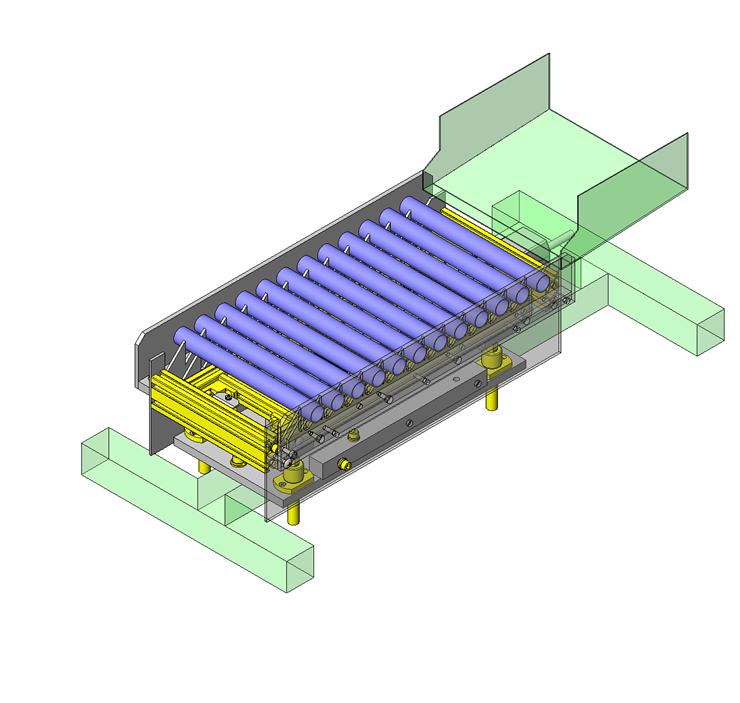
No.000080 Feeding Mechanism for Round Bars
36
Transfer workpieces with a saw tooth mechanism
Relevant category


Selection criteria
Reduces friction and wear on the inclined plane.
Available sizes
■Cam Followers - Crown Type, No Seal
| Applications | Main body | Nut | |||
|---|---|---|---|---|---|
| Material | Seal | Material | Surface treatment | ||
| Without | With | ||||
| General | 52100 Bearing Steel | ○ | ○ | 1045 Carbon Steel | Black oxide |
| 440C Stainless Steel | ○ | ○ | 304 Stainless Steel | - | |
| Low particle generation | - | ○ | |||
■Sizes and Dimensions
| Stud DIa. | Thread Dia. x Pitch | Outer ring DIa. | Outer ring width | Overall length | Circumference R |
|---|---|---|---|---|---|
| φ5 | M5×0.8 | φ13 | 9 | 23 | 250 |
| φ6 | M6×1.0 | φ16 | 11 | 28 | 500 |
| φ8 | M8x1.25 | φ19 | 11 | 32 | |
| φ10 | M10x1.25 | φ22 | 12 | 36 | |
| φ26 | |||||
| φ12 | M12x1.5 | φ30 | 14 | 40 | |
| φ32 | |||||
| φ16 | M16x1.5 | φ35 | 18 | 52 | |
| φ18 | M18×1.5 | φ40 | 20 | 58 | |
| φ20 | M20×1.5 | φ52 | 22 | 66 | 1000 |
Accuracy Info
■Cam follower accuracy
Stud Dia. tolerance: h7
Outer ring width tolerance: 0/-0.12
Outer ring Dia. tolerance: 0/-0.05
Performance info.
Load capacity and speed of cam follower
| Stud Dia. -Outer ring Dia. | Basic dynamic load rating | Basic static load rating | Max. allowable load | Track load capacity | Rotational speed limit (rpm) | |
|---|---|---|---|---|---|---|
| C(kN) | Cor(kN) | (kN) | (kN) | With Seal | Without Seal | |
| φ3−φ10 | 1.47 | 1.18 | 0.36 | 0.37 | 32900 | 47000 |
| φ4−φ12 | 2.06 | 2.05 | 0.78 | 0.47 | 25900 | 37000 |
| φ5−φ13 | 3.14 | 2.77 | 1.42 | 0.53 | 20300 | 29000 |
| φ6−φ16 | 3.59 | 3.58 | 2.11 | 1.08 | 17500 | 25000 |
| φ8−φ19 | 4.17 | 4.65 | 4.73 | 1.37 | 14000 | 20000 |
| φ10−φ22 | 5.33 | 6.78 | 5.81 | 1.67 | 11900 | 17000 |
| φ10−φ26 | 2.06 | |||||
| φ12−φ30 | 7.87 | 9.79 | 9.37 | 2.45 | 9800 | 14000 |
| φ12−φ32 | 2.74 | |||||
| φ16−φ35 | 12 | 18.3 | 17.3 | 3.14 | 7000 | 10000 |
| φ18−φ40 | 14.7 | 25.2 | 26.1 | 3.72 | 5950 | 8500 |
| φ20−φ52 | 20.7 | 34.8 | 32.1 | 8.23 | 4900 | 7000 |
Aluminum extrusions

| Product name | Aluminum Extrusion - 5 Series, Base 20, Four-Side Slots |
|---|---|
| Part number | HFS5-2020-360 |
Selection criteria
Low Weight Option.
Available sizes
■Aluminum extrusions (Overview)
| External size | Screw Dia. for extrusion slots | Length configure in 0.5mm increments | Standard | High rigidity type | Light type (Lightweight・economical) |
|---|---|---|---|---|---|
| □20 | M5 | 50-4000 | ○ | ○ | |
| □25 | ○ | ||||
| □40 | ○ | ○ | |||
| □30 | M6 | ○ | ○ | ○ | |
| □50 | ○ | ||||
| □60 | ○ | ○ | |||
| □100 | ○ | ||||
| □40 | M8 | ○ | ○ | ○ | |
| □80 | ○ | ||||
| □45 | ○ | ○ | ○ | ||
| □50 | ○ | ○ | |||
| □60 | ○ | ○ | |||
| □90 | ○ | ○ | |||
| □100 | ○ | ○ |

IDEA NOTE Transfer with saw tooth mechanism
Cylindrical workpieces are moved forward at a fixed rate as the saw tooth blades move up and down.


-

-
 TERMS AND CONDITIONS FOR USE OF CAD DATA
-
Your access to the CAD data that MISUMI Corporation (hereinafter referred to as the Company) posts on this site (including 3D CAD data, intermediate 3D CAD data and 2D CAD data; hereinafter referred to as the Data) are of products manufactured and/or sold by the Company (hereinafter referred to as the Products) assumes that you have read and accepted these terms and conditions which govern your use of the Data. If you do not agree to these terms and conditions, you must stop using this website and the Data. You must not use the Data for any unlawful purpose or in any manner inconsistent with these terms and conditions.
- 1. CAD Data
- The Data is prepared for assisting the Company's users in the CAD design process by providing dimensions and other Product information. In order to provide the best speed and stability working within this site, the Product drawings were simplified to reduce the size of the Data. For instance, some of the Products are shown without the oil groove shape, screws or spring shape. Also, please be aware that the tolerance, surface roughness and/or chamfer of the Data may vary from the actual Products.
- 2. Disclaimer on Data
- While the Company has carefully prepared the Data, accuracy of the Data is not guaranteed and is subject to the variances as described above. The Company may also modify, add or delete the Data at any time without prior notice. The Company assumes no liability for any direct, indirect, consequential or special damages that you may claim resulted from your use of the Data or any changes to or deletions of the Data regardless of the reason. The Company provides no warranty as to the quality, accuracy, functionality, safety or reliability of the combination of Products and parts. Example applications and combinations of the Products are provided for illustrative purposes only.
- 3. Copyright
-
Copyrights to the content and the Data belong to the Company or the manufacturers of the Products. The said copyright is protected by the Copyright Act and international treaties. The use (including duplication, modification, uploading, posting, transmission, distribution, licensing, sales and publishing) of the Data except for the purpose to use the Data described above without prior approval of the Company is not allowed. The Data cannot be used for any purposes (including sales promotion) except for designing your machine. If you violate this provision or the laws or regulations, the Company may prohibit you from the use of the Data, the Company’s site and/or take legal action. So long as you comply with these terms and conditions, the Company grants to you a non-exclusive, non-transferable, revocable license to access and use the Data for the sole purpose of assisting you in designing machines that incorporate products.
In case that the CAD data is found to have been to be used for any purpose other than mentioned above or against the related laws, MISUMI may take legal actions, including the one for blocking the involved user from using CAD data and from accessing to the MISUMI site. - 4. Disclaimer of Warranty
- ANY AND ALL CONTENT APPEARING ON THIS WEB SITE IS PROVIDED FOR INFORMATIONAL PURPOSES ONLY. THIS WEB SITE, ITS CONTENT AND ITS LINKS ARE PROVIDED ON AN "AS IS" AND "AS AVAILABLE" BASIS AND ARE USED ONLY AT YOUR SOLE RISK, TO THE FULLEST EXTENT PERMISSIBLE BY LAW. THE COMPANY DISCLAIMS ALL WARRANTIES, EXPRESS OR IMPLIED, OF ANY KIND, REGARDING THIS WEB SITE (INCLUDING ITS CONTENT, HARDWARE, SOFTWARE AND LINKS), INCLUDING AS TO FITNESS FOR A PARTICULAR PURPOSE, MERCHANTABILITY, TITLE, NON INFRINGEMENT, RESULTS, ACCURACY, COMPLETENESS, ACCESSIBILITY, COMPATIBILITY, SECURITY AND FREEDOM FROM COMPUTER VIRUS. THE COMPANY WILL NOT BE LIABLE FOR ANY DAMAGES OR LOSSES, INCLUDING DIRECT, INDIRECT, CONSEQUENTIAL, SPECIAL, INCIDENTAL OR PUNITIVE DAMAGES AND/OR LOST PROFITS, IN CONNECTION WITH USE OF THE INTERNET, THIS WEB SITE, ITS CONTENT OR ITS LINKS
Further, the Company will not be liable to you for any failure or delay by the Company to provide access to the Data or any of its obligations under these terms and conditions where such failure or delay is the direct or indirect result of any circumstances beyond the Company's reasonable control (and the Company's obligations will be suspended for the duration of such circumstances).
CAD Download (Unit Assembly)
CAD Download: File Format
CAD Data Limitations
-
Assembly data shows the assembly drawings in the concept design phase. The sole purpose of the data is to explain the structure and functionality of the assembly and is not considered nor to be used as a final design.
You will need to edit the Data so that it meets your specific design conditions. -
Unit assembly Data consists of some sub-assemblies.
It is configured so that each sub-assembly unit can be used as it is or edited. - The Data for fabricated parts is based on easy-to-edit dimensions and shapes in sketches and histories.
- The Data including the third-part components are made by the Company.
* The part in the frame is a sub-assembly unit.
-
Your access to the CAD data that MISUMI Corporation (hereinafter referred to as the Company) posts on this site (including 3D CAD data, intermediate 3D CAD data and 2D CAD data; hereinafter referred to as the Data) are of products manufactured and/or sold by the Company (hereinafter referred to as the Products) assumes that you have read and accepted these terms and conditions which govern your use of the Data. If you do not agree to these terms and conditions, you must stop using this website and the Data. You must not use the Data for any unlawful purpose or in any manner inconsistent with these terms and conditions.
-

- * Unit assembly Data consists of some sub-assemblies.
It is configured so that each sub-assembly unit can be used as it is or edited.
Application Overview
Purpose
- Cylindrical workpieces are fed at a fixed rate.
- This operation has both stationary and moving saw tooth blade. The moving saw tooth blades transport workpieces at a fixed rate and interval.
Target workpiece
- Shape: Aluminum rollers
- Size: O.D. φ20 x I.D. φ18 x L200mm
- Weight: 33 g
Design Specifications
Operating Conditions or Design Requirements
- Up /down stroke: 30mm
- Elevating thrust: 220N
- Cycle time: 30sec
- External dims.: W213 x D430 x H140mm
Required Performance
- Positioning accuracy: ±0.2mm
- Load weight: 22kg
Selection Criteria for Main Components
- Electric cylinder
- Electric cylinder is used when an air source is not available.
- Space saving
- The plate cam stroke only needs to be 30mm to achieve a 100mm up and down stroke.
Design Evaluation
Verification of main components
- Verify the electric cylinder thrust for the ability to raise the moving object.
- Lifting thrust calculation
- Conditional value: Moving object mass M = 22kg, Gravitational acceleration g = 9.8m/s², Plate cam angle D = 21°
Electric cylinder thrust (Max.) F = 156N
Force applicable in vertical direction: W = M x g = 22 x 9.8 = 216N
Horizontal thrust required to raise W in vertical direction: P = W x tan(D), then
P=W×tan(D)=216×tan21°=83N
Since horizontal thrust: P = 83N < Electric cylinder thrust (max.) F = 156N,
sufficient elevation force can be obtained.
the max. elevating force would be W(max) = F / tan(D) = 156 / tan21° = 406N
- Conditional value: Moving object mass M = 22kg, Gravitational acceleration g = 9.8m/s², Plate cam angle D = 21°
Other Design Consideration
- The linear guide blocks are stationary with moving rails to move the cam.
- Alum. extrusions are as a low weight option.
- Electric cylinder is used for installation in locations without air source.
Explore Similar Application Examples

-

-

-

-

-

-

-

-

-

-

-

-

-

-

-

-

-

-

-

Relevant category
-

-

-

-

-

-

-

-

-

-

-

-

-

-

-

-

-

-

-

-

-

-

-

-

-

-

-

-

-

-

-

-

-

-

-

-

-

Relevant category
-

-

-

-

-

-

-

-

-

-

-

-

-

-

-

-

-

-

-

-

-

-

-

-

-

-

-

-

-

-

-

-

-

-

-

-

-

-

-

-

-

-

-

-

-

-

-

-

-

-

-

-

-

-

-

-

-

-

-

-

-

-

-

-

-

-

-


Payment Methods
- Credit Card
-
- Bank
-
- Prompt Pay
-


Social Media
MISUMI Contact
Copyright © MISUMI Corporation All Rights Reserved.