(!) Since support from Microsoft will end on January 14 2020, Windows 7 user might not be able to use MISUMI website effectively. Please consider to update your system as ‘MISUMI Website system requirement’.


- inCAD Library Home
- > No.000059 Pick-up and Place (Suction Cup Head)
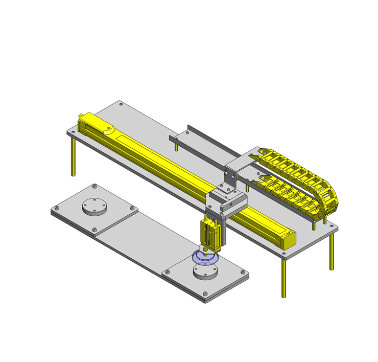
No.000059 Pick-up and Place (Suction Cup Head)
118
A pick and place mechanism with a single axis robot
Relevant category


Cylinder with guides

| Product name | Cylinders with Twin Guides |
|---|---|
| Part number | MGCLB16-50 |
| Features | Cylinders having the guides on both ends for usability. |
Selection criteria
For ease of design this was selected for as it is a complete assembly with no extra designing required.
Available sizes
■Cylinder with guides (Fixed stroke type)
| Tube I.D. | Bearing | Slide bearing | Linear bushing bearing | Cylinder width | Overall length (Shown + Stroke) | Thickness | ||||||||||||||
|---|---|---|---|---|---|---|---|---|---|---|---|---|---|---|---|---|---|---|---|---|
| St | 10 | 20 | 25 | 30 | 40 | 50 | 75 | 100 | 10 | 20 | 25 | 30 | 40 | 50 | 75 | 100 | ||||
| φ12 | ○ | ○ | - | ○ | ○ | ○ | ○ | ○ | ○ | ○ | - | ○ | ○ | ○ | ○ | ○ | 56 | 39 | 22 | |
| φ16 | ○ | ○ | - | ○ | ○ | ○ | ○ | ○ | ○ | ○ | - | ○ | ○ | ○ | ○ | ○ | 62 | 43 | 25 | |
| φ20 | - | ○ | - | ○ | ○ | ○ | ○ | ○ | - | ○ | - | ○ | ○ | ○ | ○ | ○ | 72 | 47 | 30 | |
| φ25 | - | ○ | - | ○ | ○ | ○ | ○ | ○ | - | ○ | - | ○ | ○ | ○ | ○ | ○ | 86 | 47.5 | 38 | |
| φ32 | - | - | ○ | - | - | ○ | ○ | ○ | - | - | ○ | - | - | ○ | ○ | ○ | 112 | 48 | ||
| φ50 | - | - | ○ | - | - | ○ | - | ○ | - | - | - | - | - | - | - | - | 146 | 72 | 60 | |
*Sensor sold separately
Accuracy Info
■Non-rotating accuracy of a cylinder
Non-rotational accuracy: Play in between the guide rod and the bearing is represented as the runout angle centered around the piston rod.
| Tube I.D. | Non-rotating accuracy of the tip link bar | |
|---|---|---|
| Slide bearing | Linear bushing bearing | |
| φ12 | ±0.12° | ±0.06° |
| φ16 | ±0.10° | ±0.06° |
| φ20 | ±0.09° | ±0.05° |
| φ25 | ±0.08° | ±0.05° |
| φ32 | ±0.06° | ±0.04° |
| φ50 | ±0.05° | - |
Performance info.
■Cylinder with guides operational pressure range
Min. operating pressure (Mpa): 0.1
Max. operating pressure (Mpa): 1.0
Proof pressure(MPa): 1.5
■Theoretical thrust
(N)
| Tube I.D. | Operation direction | Operating pressure (MPa) | |
|---|---|---|---|
| 0.4 | 0.5 | ||
| φ12 | Push | 45 | 57 |
| Pull | 34 | 42 | |
| φ16 | Push | 80 | 101 |
| Pull | 60 | 75 | |
| φ20 | Push | 126 | 157 |
| Pull | 94 | 118 | |
| φ25 | Push | 196 | 245 |
| Pull | 151 | 189 | |
| φ32 | Push | 322 | 402 |
| Pull | 241 | 302 | |
| φ50 | Push | 785 | 982 |
| Pull | 660 | 825 | |
■Allowable rotational torque
Indicates allowable dynamic value when the cylinder is operated while a rotational torque is applied at the tip of the guide rod.

(N・m)
| Tube I.D. | Bearing type | Stroke | |||||||
|---|---|---|---|---|---|---|---|---|---|
| 10 | 20 | 25 | 30 | 40 | 50 | 75 | 100 | ||
| φ12 | Slide bearing | 0.50 | 0.40 | - | 0.33 | 0.28 | 0.25 | 0.77 | 0.65 |
| Linear bushing | 0.41 | 0.31 | - | 0.25 | 0.69 | 0.59 | 0.40 | 0.32 | |
| φ16 | Slide bearing | 0.91 | 0.75 | - | 0.64 | 0.56 | 0.49 | 1.25 | 1.06 |
| Linear bushing | 0.76 | 0.60 | - | 0.49 | 1.14 | 1.02 | 0.79 | 0.65 | |
| φ20 | Slide bearing | - | 1.43 | - | 1.23 | 1.08 | 0.96 | 1.51 | 1.27 |
| Linear bushing | - | 1.12 | - | 0.93 | 2.12 | 1.90 | 1.50 | 1.24 | |
| φ25 | Slide bearing | - | 2.26 | - | 1.94 | 1.71 | 1.52 | 2.38 | 2.00 |
| Linear bushing | - | 1.98 | - | 1.65 | 3.75 | 3.37 | 2.68 | 2.22 | |
| φ32 | Slide bearing | - | - | 6.71 | - | - | 5.24 | 4.30 | 3.64 |
| Linear bushing | - | - | 3.61 | - | - | 2.55 | 6.48 | 5.41 | |
| φ50 | Slide bearing | - | - | 13.0 | - | - | 10.8 | - | 10.6 |
■ Allowable lateral load
Indicates allowable dynamic value when the cylinder is operated while a lateral load (load perpendicular to the guide rod) is applied at the tip of the guide rod.
(N)
| Tube I.D. | Bearing type | Stroke | |||||||
|---|---|---|---|---|---|---|---|---|---|
| 10 | 20 | 25 | 30 | 40 | 50 | 75 | 100 | ||
| φ12 | Slide bearing | 24 | 19 | - | 16 | 14 | 12 | 37 | 31 |
| Linear bushing | 20 | 15 | - | 12 | 33 | 29 | 19 | 16 | |
| φ16 | Slide bearing | 40 | 33 | - | 28 | 24 | 21 | 55 | 46 |
| Linear bushing | 33 | 26 | - | 21 | 50 | 44 | 34 | 28 | |
| φ20 | Slide bearing | - | 52 | - | 45 | 39 | 35 | 55 | 46 |
| Linear bushing | - | 41 | - | 34 | 77 | 69 | 54 | 45 | |
| φ25 | Slide bearing | - | 69 | - | 60 | 52 | 47 | 73 | 62 |
| Linear bushing | - | 61 | - | 51 | 115 | 104 | 82 | 68 | |
| φ32 | Slide bearing | - | - | 166 | - | - | 131 | 107 | 91 |
| Linear bushing | - | - | 90 | - | - | 34 | 162 | 135 | |
| φ50 | Slide bearing | - | - | 296 | - | - | 245 | - | 241 |

Suction cup with fitting

| Product name | Suction Cups - with Fitting, Spring Type, Shape K |
|---|---|
| Part number | MVPKN10 |
Selection criteria
Suitable for gripping the flat surface of the workpiece
Risk info.
Loss of suction ability due to wear and degradation
Available sizes
■Suction cup with fitting (With pad) Fixed type, Top tube connection: One touch type (Shape K)
| Body material | Surface treatment | Pad shape | Pad material |
|---|---|---|---|
| Brass | Electroless nickel plating | Standard | Nitrile rubber |
| Conductive silicon rubber | |||
| Fluorine rubber | |||
| Deep type | Nitrile rubber | ||
| Fluorine rubber |
■Sizes and Dimensions
| Pad shape | Suction pad | Port size | Overall length | Mounting thread DIA. x Pitch | |
|---|---|---|---|---|---|
| O.D. | Length | ||||
| Standard | φ2 | 4 | φ4 | 28.3 | M6×0.75 |
| φ3 | |||||
| φ4 | |||||
| φ6 | 7 | φ6 | 32.6 | M10×1.0 | |
| φ8 | 5.5 | 31.1 | |||
| φ10 | 8 | 34.1 | M12×1.0 | ||
| φ15 | 9 | 35.1 | |||
| φ20 | 10 | 37.5 | M14×1.0 | ||
| Deep type | φ20 | 11 | 38.7 | ||
| φ25 | 12 | 39.7 | |||
| φ30 | 14 | 41.7 | |||
| φ40 | 17.5 | 45.2 | |||


-

-
 TERMS AND CONDITIONS FOR USE OF CAD DATA
-
Your access to the CAD data that MISUMI Corporation (hereinafter referred to as the Company) posts on this site (including 3D CAD data, intermediate 3D CAD data and 2D CAD data; hereinafter referred to as the Data) are of products manufactured and/or sold by the Company (hereinafter referred to as the Products) assumes that you have read and accepted these terms and conditions which govern your use of the Data. If you do not agree to these terms and conditions, you must stop using this website and the Data. You must not use the Data for any unlawful purpose or in any manner inconsistent with these terms and conditions.
- 1. CAD Data
- The Data is prepared for assisting the Company's users in the CAD design process by providing dimensions and other Product information. In order to provide the best speed and stability working within this site, the Product drawings were simplified to reduce the size of the Data. For instance, some of the Products are shown without the oil groove shape, screws or spring shape. Also, please be aware that the tolerance, surface roughness and/or chamfer of the Data may vary from the actual Products.
- 2. Disclaimer on Data
- While the Company has carefully prepared the Data, accuracy of the Data is not guaranteed and is subject to the variances as described above. The Company may also modify, add or delete the Data at any time without prior notice. The Company assumes no liability for any direct, indirect, consequential or special damages that you may claim resulted from your use of the Data or any changes to or deletions of the Data regardless of the reason. The Company provides no warranty as to the quality, accuracy, functionality, safety or reliability of the combination of Products and parts. Example applications and combinations of the Products are provided for illustrative purposes only.
- 3. Copyright
-
Copyrights to the content and the Data belong to the Company or the manufacturers of the Products. The said copyright is protected by the Copyright Act and international treaties. The use (including duplication, modification, uploading, posting, transmission, distribution, licensing, sales and publishing) of the Data except for the purpose to use the Data described above without prior approval of the Company is not allowed. The Data cannot be used for any purposes (including sales promotion) except for designing your machine. If you violate this provision or the laws or regulations, the Company may prohibit you from the use of the Data, the Company’s site and/or take legal action. So long as you comply with these terms and conditions, the Company grants to you a non-exclusive, non-transferable, revocable license to access and use the Data for the sole purpose of assisting you in designing machines that incorporate products.
In case that the CAD data is found to have been to be used for any purpose other than mentioned above or against the related laws, MISUMI may take legal actions, including the one for blocking the involved user from using CAD data and from accessing to the MISUMI site. - 4. Disclaimer of Warranty
- ANY AND ALL CONTENT APPEARING ON THIS WEB SITE IS PROVIDED FOR INFORMATIONAL PURPOSES ONLY. THIS WEB SITE, ITS CONTENT AND ITS LINKS ARE PROVIDED ON AN "AS IS" AND "AS AVAILABLE" BASIS AND ARE USED ONLY AT YOUR SOLE RISK, TO THE FULLEST EXTENT PERMISSIBLE BY LAW. THE COMPANY DISCLAIMS ALL WARRANTIES, EXPRESS OR IMPLIED, OF ANY KIND, REGARDING THIS WEB SITE (INCLUDING ITS CONTENT, HARDWARE, SOFTWARE AND LINKS), INCLUDING AS TO FITNESS FOR A PARTICULAR PURPOSE, MERCHANTABILITY, TITLE, NON INFRINGEMENT, RESULTS, ACCURACY, COMPLETENESS, ACCESSIBILITY, COMPATIBILITY, SECURITY AND FREEDOM FROM COMPUTER VIRUS. THE COMPANY WILL NOT BE LIABLE FOR ANY DAMAGES OR LOSSES, INCLUDING DIRECT, INDIRECT, CONSEQUENTIAL, SPECIAL, INCIDENTAL OR PUNITIVE DAMAGES AND/OR LOST PROFITS, IN CONNECTION WITH USE OF THE INTERNET, THIS WEB SITE, ITS CONTENT OR ITS LINKS
Further, the Company will not be liable to you for any failure or delay by the Company to provide access to the Data or any of its obligations under these terms and conditions where such failure or delay is the direct or indirect result of any circumstances beyond the Company's reasonable control (and the Company's obligations will be suspended for the duration of such circumstances).
CAD Download (Unit Assembly)
CAD Download: File Format
CAD Data Limitations
-
Assembly data shows the assembly drawings in the concept design phase. The sole purpose of the data is to explain the structure and functionality of the assembly and is not considered nor to be used as a final design.
You will need to edit the Data so that it meets your specific design conditions. -
Unit assembly Data consists of some sub-assemblies.
It is configured so that each sub-assembly unit can be used as it is or edited. - The Data for fabricated parts is based on easy-to-edit dimensions and shapes in sketches and histories.
- The Data including the third-part components are made by the Company.
* The part in the frame is a sub-assembly unit.
-
Your access to the CAD data that MISUMI Corporation (hereinafter referred to as the Company) posts on this site (including 3D CAD data, intermediate 3D CAD data and 2D CAD data; hereinafter referred to as the Data) are of products manufactured and/or sold by the Company (hereinafter referred to as the Products) assumes that you have read and accepted these terms and conditions which govern your use of the Data. If you do not agree to these terms and conditions, you must stop using this website and the Data. You must not use the Data for any unlawful purpose or in any manner inconsistent with these terms and conditions.
-

- * Unit assembly Data consists of some sub-assemblies.
It is configured so that each sub-assembly unit can be used as it is or edited.
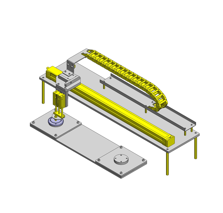
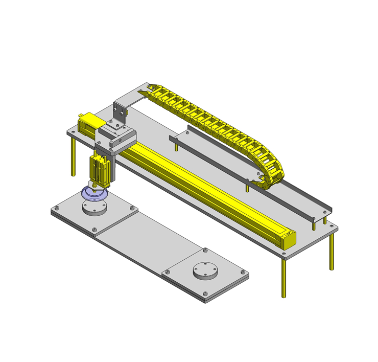
Application Overview
Purpose
- Pick and place transfer with suction holder.
Target workpiece
- Plastic disc.
- Workpiece size: φ84, height 13mm
- Workpiece weight: 20g
Design Specifications
Operating Conditions or Design Requirements
- Stroke: 500mm
- External dims.: W990 x D347 x H311mm
Required Performance
- Positioning accuracy: ±0.9mm
- Robot transfer weight: 3kg
Selection Criteria for Main Components
- A single axis robot is used since multiple positions are needed over a single stroke.
Design Evaluation
Verification of main components
- Select a suction holder appropriate for suction hold the workpiece and a robot that satisfies the transfer specifications (Load capacity, speed , stroke).
- Selection of suction holder
- Conditional value: Workpiece weight Mw = 0.02kg
Gravitational acceleration g = 9.8m/s²
Approx. suction force Fr = Mw × g × 1.2 = 0.02 × 9.8 × 1.2 = 0.24N *1.2 is a 20% buffer since its approximate.
Temporary pad DIA. selection: φ10mm
Pad area A: 0.785cm²
When the vacuum Va is assumed to be: 40-kPa, - Suction force Fv= (A×Va) / 101 × 10.13 = (0.785 × 40) / 101 × 10.13 =3.15N
Fv>>Fr thus no problem.
- Conditional value: Workpiece weight Mw = 0.02kg
- Selection of single axis robot
- ① Load capacity → Select from [Max. load capacity]: 3kg
② Stroke → Select from [Stroke]: 500mm
③ Cycle time → Select from [Cycle time graph] 1.2sec
RS220-C1-N-3-700 is selected.
④ Detail confirmation
Overhang: At 4kg, 53.5mm against allowable value of 120mm, thus no problem.
- ① Load capacity → Select from [Max. load capacity]: 3kg
Other Design Consideration
- With the longer stroke use a cable carrier to prevent the wiring harness from getting tangled or damaged.
- Due to deterioration of the suction cup, include a pressure switch to monitor contact, also perform periodical maintenance to prevent suction loss.
Explore Similar Application Examples

-

-

-

-

-

-

-

-

-

-

-

-

-

-

-

-

-

-

-

Relevant category
-

-

-

-

-

-

-

-

-

-

-

-

-

-

-

-

-

-

-

-

-

-

-

-

-

-

-

-

-

-

-

-

-

-

Relevant category
-

-

-

-

-

-

-

-

-

-

-

-

-

-

-

-

-

-

-

-

-

-

-

-

-

-

-

-

-

-

-

-

-

-

-

-

-

-

-

-

-

-

-

-

-

-

-

-

-

-

-

-


Payment Methods
- Credit Card
-
- Bank
-
- Prompt Pay
-


Social Media
MISUMI Contact
Copyright © MISUMI Corporation All Rights Reserved.