(!) Since support from Microsoft will end on January 14 2020, Windows 7 user might not be able to use MISUMI website effectively. Please consider to update your system as ‘MISUMI Website system requirement’.


- inCAD Library Home
- > No.000058 Rotator Table
No.000058 Rotator Table
60
A rotary table with a linkage mechanism
Relevant category


Clamp link

| Product name | Clamp Links - For Rod End Bearing |
|---|---|
| Part number | CLKB15-6-100 |
Selection criteria
Suitable as a rotation drive arm.
Risk info.
Slippage due to inadequate clamping force.
Available sizes
■Clamp link, for rod end bearing, Standard type
| Material | Surface treatment |
|---|---|
| 1045 Carbon Steel | Black oxide |
| Electroless nickel plating | |
| 304 Stainless Steel | − |
| 6063 Aluminum Alloy | − |
■Sizes and Dimensions
| Clamp bore DIa. (Lg. bore DIa.) | Joint bore DIa. | Hole pitch(L) | Thickness | Width |
|---|---|---|---|---|
| (Sm. bore DIa.) | Configure in 1mm increments | |||
| φ12 | φ5, 6, 8, 10, 12 | 20-150 | 12 | 18 |
| φ14 | φ6, 8, 10, 12, 14 | 22 | ||
| φ15 | φ6, 8, 10, 12, 14, 15 | |||
| φ16 | φ8, 10, 12, 14, 15, 16 | 30-150 | ||
| φ18 | φ8, 10, 12, 14, 15, 16, 18 | 25 |
■Overall length (L = Hole pitch)
| Clamp bore DIa. | Joint bore DIa. | ||||||||
|---|---|---|---|---|---|---|---|---|---|
| φ5 | φ6 | φ8 | φ10 | φ12 | φ14 | φ15 | φ16 | φ18 | |
| φ12 | L+23 | L+24 | L+25 | L+27 | L+30 | ||||
| φ14 | L+27 | L+28 | L+29 | L+31 | L+32 | ||||
| φ15 | L+27 | L+28 | L+30 | L+32 | L+34 | L+35 | |||
| φ16 | L+30 | L+31 | L+33 | L+34 | L+35 | L+36 | |||
| φ18 | L+32 | L+33 | L+35 | L+36 | L+37 | L+38 | L+40 | ||
Accuracy Info
Clamp bore Dia. (Lg. bore Dia.) tolerance: H7
Joint bore Dia. (Sm. bore Dia.) tolerance: +0.2/0mm
Hole pitch tolerance: ±0.1mm

Rod end bearing
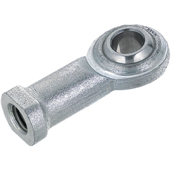
| Product name | Rod End Bearings - Standard |
|---|---|
| Part number | PHSCM8 |
Selection criteria
Component is suitable for Non-directional Load
Available sizes
■Rod end bearing, Threaded, short type
| Thread type | Thread direction | Bearing type | Material | ||
|---|---|---|---|---|---|
| Holder | Spherical inner ring | Bushing(Liner) | |||
| Threaded, Tapped | Right hand thread, Left hand thread | Steel | 1035 Carbon Steel (Trivalent chromate) | 52100 Bearing Steel (58HRC-) | Special copper alloy |
| Oil-free | Tetrafluoroethylene resin | ||||
| Stainless steel Oil-free | 303 Stainless Steel | 440C Stainless Steel (58HRC-) | |||
■Sizes and Dimensions
| Thread type | Shaft bore DIa. | O.D. | Overall length | Thread DIa. x pitch | Thread length | ||
|---|---|---|---|---|---|---|---|
| Steel | Oil-free | Stainless steel oil-free | |||||
| Tapped | φ5 | φ16 | 35 | M5×0.8 | 14 | 14 | 12.5 |
| φ6 | φ18 | 39 | M6×1.0 | 13.5 | |||
| φ8 | φ22 | 47 | M8×1.25 | 17 | 17 | 16 | |
| φ10 | φ26 | 56 | M10×1.5 | 21 | 21 | 19 | |
| M10×1.25 | − | − | |||||
| φ12 | φ30 | 65 | M12×1.75 | 24 | 24 | 24 | |
| Threaded | φ5 | φ16 | 41 | M5×0.8 | 20 | 20 | 6 |
| φ6 | φ18 | 45 | M6×1.0 | 22 | 22 | 6.75 | |
| φ8 | φ22 | 53 | M8×1.25 | 25 | 25 | 9 | |
| φ10 | φ26 | 61 | M10×1.5 | 29 | 29 | 10.5 | |
| M10×1.25 | - | − | |||||
| φ12 | 30 | 69 | M12×1.75 | 33 | 33 | 12 | |
* Oil-free version of shaft bore DIa. φ10, M10 x 1.25, stainless steel oil free are not available.
Accuracy Info
■Rod end bearing standard type accuracy info.
Bore dims tolerance: H7
Shaft fits:
| App. condition | Shaft dims. tolerance | |
|---|---|---|
| Steel | Oil-free, Stainless steel oil-free | |
| Normal load | h7 | p6 |
| Non-directional Load | p6 | p6 |
Clearance:
| Direction | Steel | Oil-free, Stainless steel oil-free |
|---|---|---|
| Radial | 0.035 or less | 0.045 or less |
| Axial | 0.1 or less | 0.1 or less |
Performance info.
■Rod end bearing Standard type static load capacity
| Thread type | Shaft bore DIa. | Screw DIa. X Pitch | Static load capacity radial Cs [kN] | ||
|---|---|---|---|---|---|
| Steel | Oil-free | Stainless steel oil-free | |||
| Tapped | φ5 | M5×0.8 | 5.59 | 3.92 | 0.98 |
| φ6 | M6×1.0 | 6.86 | 5 | 1.44 | |
| φ8 | M8×1.25 | 9.8 | 7.45 | 2.69 | |
| φ10 | M10×1.5 | 13.2 | 9.41 | 4.16 | |
| M10×1.25 | − | − | |||
| φ12 | M12×1.75 | 16.7 | 11 | 5.88 | |
| Threaded | φ5 | M5×0.8 | 3.43 | 3.43 | 0.98 |
| φ6 | M6×1.0 | 4.9 | 4.9 | 1.44 | |
| φ8 | M8×1.25 | 6.86 | 6.86 | 2.69 | |
| φ10 | M10×1.5 | 10.8 | 9.41 | 4.16 | |
| M10×1.25 | − | − | |||
| φ12 | M12×1.75 | 16.7 | 11 | 5.88 | |
* Oil-free version of shaft bore DIa. φ10, M10 x 1.25, stainless steel oil free are not available.


-

-
 TERMS AND CONDITIONS FOR USE OF CAD DATA
-
Your access to the CAD data that MISUMI Corporation (hereinafter referred to as the Company) posts on this site (including 3D CAD data, intermediate 3D CAD data and 2D CAD data; hereinafter referred to as the Data) are of products manufactured and/or sold by the Company (hereinafter referred to as the Products) assumes that you have read and accepted these terms and conditions which govern your use of the Data. If you do not agree to these terms and conditions, you must stop using this website and the Data. You must not use the Data for any unlawful purpose or in any manner inconsistent with these terms and conditions.
- 1. CAD Data
- The Data is prepared for assisting the Company's users in the CAD design process by providing dimensions and other Product information. In order to provide the best speed and stability working within this site, the Product drawings were simplified to reduce the size of the Data. For instance, some of the Products are shown without the oil groove shape, screws or spring shape. Also, please be aware that the tolerance, surface roughness and/or chamfer of the Data may vary from the actual Products.
- 2. Disclaimer on Data
- While the Company has carefully prepared the Data, accuracy of the Data is not guaranteed and is subject to the variances as described above. The Company may also modify, add or delete the Data at any time without prior notice. The Company assumes no liability for any direct, indirect, consequential or special damages that you may claim resulted from your use of the Data or any changes to or deletions of the Data regardless of the reason. The Company provides no warranty as to the quality, accuracy, functionality, safety or reliability of the combination of Products and parts. Example applications and combinations of the Products are provided for illustrative purposes only.
- 3. Copyright
-
Copyrights to the content and the Data belong to the Company or the manufacturers of the Products. The said copyright is protected by the Copyright Act and international treaties. The use (including duplication, modification, uploading, posting, transmission, distribution, licensing, sales and publishing) of the Data except for the purpose to use the Data described above without prior approval of the Company is not allowed. The Data cannot be used for any purposes (including sales promotion) except for designing your machine. If you violate this provision or the laws or regulations, the Company may prohibit you from the use of the Data, the Company’s site and/or take legal action. So long as you comply with these terms and conditions, the Company grants to you a non-exclusive, non-transferable, revocable license to access and use the Data for the sole purpose of assisting you in designing machines that incorporate products.
In case that the CAD data is found to have been to be used for any purpose other than mentioned above or against the related laws, MISUMI may take legal actions, including the one for blocking the involved user from using CAD data and from accessing to the MISUMI site. - 4. Disclaimer of Warranty
- ANY AND ALL CONTENT APPEARING ON THIS WEB SITE IS PROVIDED FOR INFORMATIONAL PURPOSES ONLY. THIS WEB SITE, ITS CONTENT AND ITS LINKS ARE PROVIDED ON AN "AS IS" AND "AS AVAILABLE" BASIS AND ARE USED ONLY AT YOUR SOLE RISK, TO THE FULLEST EXTENT PERMISSIBLE BY LAW. THE COMPANY DISCLAIMS ALL WARRANTIES, EXPRESS OR IMPLIED, OF ANY KIND, REGARDING THIS WEB SITE (INCLUDING ITS CONTENT, HARDWARE, SOFTWARE AND LINKS), INCLUDING AS TO FITNESS FOR A PARTICULAR PURPOSE, MERCHANTABILITY, TITLE, NON INFRINGEMENT, RESULTS, ACCURACY, COMPLETENESS, ACCESSIBILITY, COMPATIBILITY, SECURITY AND FREEDOM FROM COMPUTER VIRUS. THE COMPANY WILL NOT BE LIABLE FOR ANY DAMAGES OR LOSSES, INCLUDING DIRECT, INDIRECT, CONSEQUENTIAL, SPECIAL, INCIDENTAL OR PUNITIVE DAMAGES AND/OR LOST PROFITS, IN CONNECTION WITH USE OF THE INTERNET, THIS WEB SITE, ITS CONTENT OR ITS LINKS
Further, the Company will not be liable to you for any failure or delay by the Company to provide access to the Data or any of its obligations under these terms and conditions where such failure or delay is the direct or indirect result of any circumstances beyond the Company's reasonable control (and the Company's obligations will be suspended for the duration of such circumstances).
CAD Download (Unit Assembly)
CAD Download: File Format
CAD Data Limitations
-
Assembly data shows the assembly drawings in the concept design phase. The sole purpose of the data is to explain the structure and functionality of the assembly and is not considered nor to be used as a final design.
You will need to edit the Data so that it meets your specific design conditions. -
Unit assembly Data consists of some sub-assemblies.
It is configured so that each sub-assembly unit can be used as it is or edited. - The Data for fabricated parts is based on easy-to-edit dimensions and shapes in sketches and histories.
- The Data including the third-part components are made by the Company.
* The part in the frame is a sub-assembly unit.
-
Your access to the CAD data that MISUMI Corporation (hereinafter referred to as the Company) posts on this site (including 3D CAD data, intermediate 3D CAD data and 2D CAD data; hereinafter referred to as the Data) are of products manufactured and/or sold by the Company (hereinafter referred to as the Products) assumes that you have read and accepted these terms and conditions which govern your use of the Data. If you do not agree to these terms and conditions, you must stop using this website and the Data. You must not use the Data for any unlawful purpose or in any manner inconsistent with these terms and conditions.
-

- * Unit assembly Data consists of some sub-assemblies.
It is configured so that each sub-assembly unit can be used as it is or edited.
Application Overview
Purpose
- Rotate workpieces 90 degrees using an air cylinder and a linkage system.
Target workpiece
- Plastic case.
- Approx. size: 60 x 80 x 20 mm
Design Specifications
Operating Conditions or Design Requirements
- External dims.: W320 x D550 x H129 mm
Required Performance
- Workpiece weight: 0.1 kg
Selection Criteria for Main Components
- Bearing with housing
- A bearing with housing is used to achieve smooth rotary motion.
Design Evaluation
Verification of main components
- The selection criteria for the cylinder are the workpiece load and the required stroke.
- Cylinder bore selection
- Conditional value:
Workpiece weight MW = 0.1 kg
Table weight MT = 7.9 kg
Bearing friction coefficient μ = 0.05
Gravitation acceleration g = 9.8 m/s²
Operating pressure P = 0.4 MPa
Operating load F = μMg, F = 0.05 × (0.1 + 7.9) × 9.8 = 3.92N
If safety ratio is 5, select F0=3.92×5=19.6N or more.
Cylinder bore D0 = √(1.274 × F0 / P) thus、D0 = √(1.274 × 19.6 / 0.4)= 7.9 mm
Therefore, the cylinder bore dia. should be 7.9 mm or larger.
- Conditional value:
- Cylinder stroke selection
- Conditional values:
Distance from rotation center to cylinder rod end (Operating radius) r = 100 mm
Operating angle θ=90 °
Length of hypotenuse a = 2 x r x sin (θ / 2) thus a = 2 × 100 × 0.707 = 141.4 mm
Therefore, the stroke should be 141.4 mm or larger.
- Conditional values:
- Selection results
- Cylinder bore --- φ20 mm, Stroke --- 150 mm
T-shaped clevis type is selected for rocking mechanism.
- Cylinder bore --- φ20 mm, Stroke --- 150 mm
Other Design Consideration
- Swing angle is adjusted with locating bolt as a stopper.
Explore Similar Application Examples

-

-

-

-

-

-

-

-

-

-

-

-

-

-

-

-

-

-

-

Relevant category
-

-

-

-

-

-

-

-

-

-

-

-

-

-

-

-

-

-

-

-

-

-

-

-

-

-

-

-

-

-

-

-

-

-

-

-

-

Relevant category
-

-

-

-

-

-

-

-

-

-

-

-

-

-

-

-

-

-

-

-

-

-

-

-

-

-

-

-

-

-

-

-

-

-

-

-

-

-

-

-

-

-

-

-

-

-

-

-

-

-

-

-

-

-

-

-

-

-

-

-

-

-

-

-

-

-

-


Payment Methods
- Credit Card
-
- Bank
-
- Prompt Pay
-


Social Media
MISUMI Contact
Copyright © MISUMI Corporation All Rights Reserved.