(!) Since support from Microsoft will end on January 14 2020, Windows 7 user might not be able to use MISUMI website effectively. Please consider to update your system as ‘MISUMI Website system requirement’.


- inCAD Library Home
- > No.000050 Adjustment Mechanism
No.000050 Adjustment Mechanism
29
Adjusting the angle at the offset center point.
Relevant category


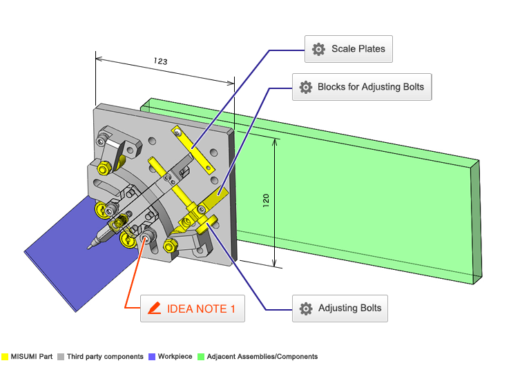
Adjusting Bolts
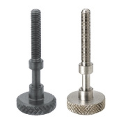
| Product name | Adjusting Bolts- Knurled Knobs |
|---|---|
| Part number | AJSTKS6-50 |
Selection criteria
Effective for Precise Adjustment
Available sizes
■Adjusting Bolts- Knurled Knobs
| Screw Type | Material | Surface Treatment |
|---|---|---|
| Coarse Thread | 1045 Carbon Steel | Black Oxide |
| Electroless Nickel Plating | ||
| 304 Stainless Steel | − |
■Sizes and Dimensions
| Screw Dia. (coarse) | Thread Length (5mm increments) | Block Bearing Part | Knob | ||
|---|---|---|---|---|---|
| Diameter | Length | Thickness | O.D. | ||
| M3 | 10〜20 | φ2.5 | 7 | 4 | φ16 |
| M4 | 10〜30 | φ3.5 | |||
| M5 | 10〜40 | φ4.5 | 9 | 6 | φ20 |
| M6 | 15〜50 | φ5.5 | |||
| M8 | 20〜50 | φ7.5 | 12 | ||
Accuracy Info
■Accuracy of the Adjusting Bolts
Block Support
Shaft Dia. Tolerance: -0.1/-0.2
Length Tolerance: +0.2/+0.1
Surface Roughness: Ra1.6

Blocks for Adjusting Bolts
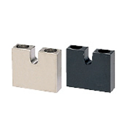
| Product name | Blocks for Adjusting Bolts- Standard Type |
|---|---|
| Part number | AJKCM6-30 |
Selection criteria
Effective for Precise Adjustment Manually
Available sizes
■Blocks for Adjusting Bolts- Standard Type
| Screw Type | Material | Surface Treatment |
|---|---|---|
| Coarse Thread | 1045 Carbon Steel | Black Oxide |
| Electroless Nickel Plating | ||
| 304 Stainless Steel | − |
■Sizes and Dimensions
| (applicable bolt screw dia.) | Bolt Bearing Slot Width | Center Height [H] | Overall Height ([H] + listed below) | Overall Thickness | Overall Width | ||||||||
|---|---|---|---|---|---|---|---|---|---|---|---|---|---|
| 5 | 6 | 8 | 10 | 12 | 15 | 20 | 25 | 30 | |||||
| M3 | 2.5 | ○ | ○ | ○ | 5 | 7 | 26 | ||||||
| M4 | 3.5 | ○ | ○ | ○ | ○ | ||||||||
| M5 | 4.5 | ○ | ○ | ○ | ○ | ○ | 6 | 9 | 32 | ||||
| M6 | 5.5 | ○ | ○ | ○ | ○ | ○ | ○ | ||||||
| M8 | 7.5 | ○ | ○ | ○ | ○ | ○ | 8 | 12 | 38 | ||||
| M10 | 9.5 | ○ | ○ | ○ | ○ | ○ | 10 | 16 | 50 | ||||
| M12 | 11.5 | ○ | ○ | ○ | ○ | ○ | 11 | 19 | 65 | ||||
| M16 | 15.5 | ○ | ○ | ○ | ○ | ||||||||
Accuracy Info
■Accuracy of Blocks for Adjusting Bolts
Slot Width Tolerance: +0.1/0
Overall Thickness Tolerance: 0/-0.2

Scale Plates
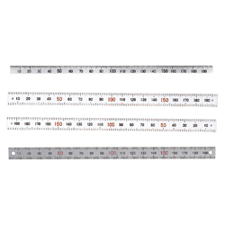
| Product name | Scale Plates |
|---|---|
| Part number | MEPCSH-LC48-HC |
Selection criteria
Provides measure scale
Available sizes
■Scale Plates
| Width | Scale Type | Material | Plate Thickness | Length |
|---|---|---|---|---|
| 8 | Zero at Left | 304 Stainless Steel | 0.5 | 100・200 |
| Zero at Right | 100・200 | |||
| Center Divided | 300 | |||
| 12 | Zero at Left | 100・200 | ||
| Zero at Right | 100・200 | |||
| Center Divided | 300 |
* Adhesive tapes are not provided.
Use the Ø3.4 x 2 screw mounting holes (5mm from the both ends).
* Length cut is available as alterations.

-
 TERMS AND CONDITIONS FOR USE OF CAD DATA
-
Your access to the CAD data that MISUMI Corporation (hereinafter referred to as the Company) posts on this site (including 3D CAD data, intermediate 3D CAD data and 2D CAD data; hereinafter referred to as the Data) are of products manufactured and/or sold by the Company (hereinafter referred to as the Products) assumes that you have read and accepted these terms and conditions which govern your use of the Data. If you do not agree to these terms and conditions, you must stop using this website and the Data. You must not use the Data for any unlawful purpose or in any manner inconsistent with these terms and conditions.
- 1. CAD Data
- The Data is prepared for assisting the Company's users in the CAD design process by providing dimensions and other Product information. In order to provide the best speed and stability working within this site, the Product drawings were simplified to reduce the size of the Data. For instance, some of the Products are shown without the oil groove shape, screws or spring shape. Also, please be aware that the tolerance, surface roughness and/or chamfer of the Data may vary from the actual Products.
- 2. Disclaimer on Data
- While the Company has carefully prepared the Data, accuracy of the Data is not guaranteed and is subject to the variances as described above. The Company may also modify, add or delete the Data at any time without prior notice. The Company assumes no liability for any direct, indirect, consequential or special damages that you may claim resulted from your use of the Data or any changes to or deletions of the Data regardless of the reason. The Company provides no warranty as to the quality, accuracy, functionality, safety or reliability of the combination of Products and parts. Example applications and combinations of the Products are provided for illustrative purposes only.
- 3. Copyright
-
Copyrights to the content and the Data belong to the Company or the manufacturers of the Products. The said copyright is protected by the Copyright Act and international treaties. The use (including duplication, modification, uploading, posting, transmission, distribution, licensing, sales and publishing) of the Data except for the purpose to use the Data described above without prior approval of the Company is not allowed. The Data cannot be used for any purposes (including sales promotion) except for designing your machine. If you violate this provision or the laws or regulations, the Company may prohibit you from the use of the Data, the Company’s site and/or take legal action. So long as you comply with these terms and conditions, the Company grants to you a non-exclusive, non-transferable, revocable license to access and use the Data for the sole purpose of assisting you in designing machines that incorporate products.
In case that the CAD data is found to have been to be used for any purpose other than mentioned above or against the related laws, MISUMI may take legal actions, including the one for blocking the involved user from using CAD data and from accessing to the MISUMI site. - 4. Disclaimer of Warranty
- ANY AND ALL CONTENT APPEARING ON THIS WEB SITE IS PROVIDED FOR INFORMATIONAL PURPOSES ONLY. THIS WEB SITE, ITS CONTENT AND ITS LINKS ARE PROVIDED ON AN "AS IS" AND "AS AVAILABLE" BASIS AND ARE USED ONLY AT YOUR SOLE RISK, TO THE FULLEST EXTENT PERMISSIBLE BY LAW. THE COMPANY DISCLAIMS ALL WARRANTIES, EXPRESS OR IMPLIED, OF ANY KIND, REGARDING THIS WEB SITE (INCLUDING ITS CONTENT, HARDWARE, SOFTWARE AND LINKS), INCLUDING AS TO FITNESS FOR A PARTICULAR PURPOSE, MERCHANTABILITY, TITLE, NON INFRINGEMENT, RESULTS, ACCURACY, COMPLETENESS, ACCESSIBILITY, COMPATIBILITY, SECURITY AND FREEDOM FROM COMPUTER VIRUS. THE COMPANY WILL NOT BE LIABLE FOR ANY DAMAGES OR LOSSES, INCLUDING DIRECT, INDIRECT, CONSEQUENTIAL, SPECIAL, INCIDENTAL OR PUNITIVE DAMAGES AND/OR LOST PROFITS, IN CONNECTION WITH USE OF THE INTERNET, THIS WEB SITE, ITS CONTENT OR ITS LINKS
Further, the Company will not be liable to you for any failure or delay by the Company to provide access to the Data or any of its obligations under these terms and conditions where such failure or delay is the direct or indirect result of any circumstances beyond the Company's reasonable control (and the Company's obligations will be suspended for the duration of such circumstances).
CAD Download (Unit Assembly)
CAD Download: File Format
CAD Data Limitations
-
Assembly data shows the assembly drawings in the concept design phase. The sole purpose of the data is to explain the structure and functionality of the assembly and is not considered nor to be used as a final design.
You will need to edit the Data so that it meets your specific design conditions. -
Unit assembly Data consists of some sub-assemblies.
It is configured so that each sub-assembly unit can be used as it is or edited. - The Data for fabricated parts is based on easy-to-edit dimensions and shapes in sketches and histories.
- The Data including the third-part components are made by the Company.
* The part in the frame is a sub-assembly unit.
-
Your access to the CAD data that MISUMI Corporation (hereinafter referred to as the Company) posts on this site (including 3D CAD data, intermediate 3D CAD data and 2D CAD data; hereinafter referred to as the Data) are of products manufactured and/or sold by the Company (hereinafter referred to as the Products) assumes that you have read and accepted these terms and conditions which govern your use of the Data. If you do not agree to these terms and conditions, you must stop using this website and the Data. You must not use the Data for any unlawful purpose or in any manner inconsistent with these terms and conditions.
-

- * Unit assembly Data consists of some sub-assemblies.
It is configured so that each sub-assembly unit can be used as it is or edited.
Application Overview
Purpose
- Purpose
- This adjustment mechanism is mounted to a loader and adjusts the inclination angle of a dispenser.
- Operation
- By loosening the rotary plate fixing bolt and turning the adjusting bolt, the inclination angle of the dispenser is adjusted.
Points for use
- Manual angle adjustment.
Target workpiece
- Shape: circuit board
- Size: W65 x D20 x t1.6mm
- Weight:5g
Design Specifications
Operating Conditions or Design Requirements
- Dispenser inclination angle adjustment: 45°±8° (37° to 53°)
- Outer dimensions: W123 x D120 x H56mm
Required Performance
- Depends on the positioning accuracy of the loader, etc.
Selection Criteria for Main Components
- Cam Follower
- A cam follower (CFFRS6-16) that has an outer ring thickness suitable for pressing the rotary plate (thickness: 13mm) and a size small enough to be mounted on this mechanism is selected.
Design Evaluation
Verification of main components
- Verify that the rotary arm and adjusting bolt can create the required inclination angle resolution.
- Calculation of resolution of angle adjustment mechanism.
- Conditional value: adjustable angle θ = 8°, adjusting bolt thread diameter M6, pitch of M6 thread P = 1mm, movable range of adjusting nut L = 16.4mm, distance between rotation center of rotary arm and adjusting bolt (rotary arm length) R = 117mm
- As the resolution at center of adjustment range: Δθ1, and the travel distance per rotation of adjusting bolt = pitch of M6 thread P = 1, sinΔθ1 = P/R = 1
Δθ1 = sin-1(P/R) = sin-1(1/117) = 0.490°/rotation - Where resolution at adjustment range limit: Δθ2, angle formed by rotary arm and adjustment range center : α, distance between adjusting nut and adjustment range center: L = 16.4, angle at center formed by rotary arm adjustment range center and arm travel made when adjusting bolt is rotated one revolution: β, as α - β = Δθ2 and sinα = L/R, sinβ = (L - P)/R,
Δθ2 = α - β = sin-1(L/R) - sin-1((L - P)/R) = sin-1(16.4/117) - sin-1 ((16.4 - 1)/117) = 8.0578 - 7.5634 = 0.494°/rotation
Other Design Consideration
- Applying a preload to the cam follower on the pushing side ensures the adjustment mechanism will not have backlash in the radial direction.
Explore Similar Application Examples


Payment Methods
- Credit Card
-
- Bank
-
- Prompt Pay
-


Social Media
MISUMI Contact
Copyright © MISUMI Corporation All Rights Reserved.