(!) Since support from Microsoft will end on January 14 2020, Windows 7 user might not be able to use MISUMI website effectively. Please consider to update your system as ‘MISUMI Website system requirement’.


- inCAD Library Home
- > No.000039 Roller Conveyor with Powered Rollers
No.000039 Roller Conveyor with Powered Rollers
154
154
Combination of free-running rollers and motor powered rollers reduce the number of drive rollers
Relevant category


Conveyor rollers
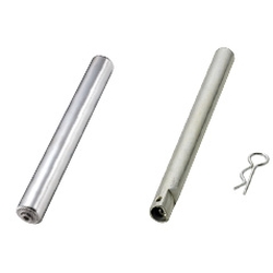
| Product name | Conveyer Roller Shafts - Hollow |
|---|---|
| Part number | HROJS38-413 |
| Features | Set of Conveyor Rollers and Economical Hollow Rollers. |
* Orange colored cells in the table below indicate the part numbers used in this example.
Selection criteria
Configurable conveyor rollers allow you to have the dimensional freedom of custom with the cost of standard.
Available sizes
■Conveyor rollers (Shaft & roller sets)
| Material | Surface treatment | Bearing | |||
|---|---|---|---|---|---|
| Roller | Shaft | Pin | Roller・Shaft・Pin | ||
| Core material | Wheel | ||||
| Carbon Steel | Steel | Steel | Steel | Trivalent chromate plating | Pressed bearing |
■Conveyor rollers (Shaft & roller sets)
| Roller length | Name No. | Roller O.D. | Shaft bore DIA. | Shaft length | Shaft(With pin) | |
|---|---|---|---|---|---|---|
| Nominal DIA. | Actual DIA. | |||||
| 113 163 213 263 313 413 513 | 19 | φ19.1 | φ6.2 | Roller length+22 | φ6 | φ5.9 |
| 22 | φ22.2 | |||||
| 28 | φ28.6 | φ8.2 | Roller length+22 | φ8 | φ7.85 | |
| 38 | φ38.1 | φ12.2 | Roller length+27 | φ12 | φ11.8 | |
| 42 | φ42.7 | |||||
| 50 | φ50.8 | |||||
| 57 | φ57.2 | |||||
*163 and 263 lengths for nominal No.22 are not available.
Performance info.
Roller Strength for Reference (N)
(N)
| Roller length(mm) | |||||||
|---|---|---|---|---|---|---|---|
| Name No. | 113 | 163 | 213 | 263 | 313 | 413 | 513 |
| 19 | 431 | 318 | 205 | 436 | 343 | 294 | 206 |
| 22 | 431 | − | 205 | − | 343 | 294 | 206 |
| 28 | 490 | 490 | 490 | 450 | 687 | 588 | 412 |
| 38 | 1342 | 1342 | 1342 | 1132 | 922 | 785 | 588 |
| 42 | 1667 | 1628 | 1589 | 1310 | 1030 | 883 | 745 |
| 50 | 1716 | 1628 | 1648 | 1584 | 1520 | 1442 | 1147 |
| 57 | 2354 | 2206 | 2059 | 1912 | 1765 | 1471 | 1157 |


-
 TERMS AND CONDITIONS FOR USE OF CAD DATA
-
Your access to the CAD data that MISUMI Corporation (hereinafter referred to as the Company) posts on this site (including 3D CAD data, intermediate 3D CAD data and 2D CAD data; hereinafter referred to as the Data) are of products manufactured and/or sold by the Company (hereinafter referred to as the Products) assumes that you have read and accepted these terms and conditions which govern your use of the Data. If you do not agree to these terms and conditions, you must stop using this website and the Data. You must not use the Data for any unlawful purpose or in any manner inconsistent with these terms and conditions.
- 1. CAD Data
- The Data is prepared for assisting the Company's users in the CAD design process by providing dimensions and other Product information. In order to provide the best speed and stability working within this site, the Product drawings were simplified to reduce the size of the Data. For instance, some of the Products are shown without the oil groove shape, screws or spring shape. Also, please be aware that the tolerance, surface roughness and/or chamfer of the Data may vary from the actual Products.
- 2. Disclaimer on Data
- While the Company has carefully prepared the Data, accuracy of the Data is not guaranteed and is subject to the variances as described above. The Company may also modify, add or delete the Data at any time without prior notice. The Company assumes no liability for any direct, indirect, consequential or special damages that you may claim resulted from your use of the Data or any changes to or deletions of the Data regardless of the reason. The Company provides no warranty as to the quality, accuracy, functionality, safety or reliability of the combination of Products and parts. Example applications and combinations of the Products are provided for illustrative purposes only.
- 3. Copyright
-
Copyrights to the content and the Data belong to the Company or the manufacturers of the Products. The said copyright is protected by the Copyright Act and international treaties. The use (including duplication, modification, uploading, posting, transmission, distribution, licensing, sales and publishing) of the Data except for the purpose to use the Data described above without prior approval of the Company is not allowed. The Data cannot be used for any purposes (including sales promotion) except for designing your machine. If you violate this provision or the laws or regulations, the Company may prohibit you from the use of the Data, the Company’s site and/or take legal action. So long as you comply with these terms and conditions, the Company grants to you a non-exclusive, non-transferable, revocable license to access and use the Data for the sole purpose of assisting you in designing machines that incorporate products.
In case that the CAD data is found to have been to be used for any purpose other than mentioned above or against the related laws, MISUMI may take legal actions, including the one for blocking the involved user from using CAD data and from accessing to the MISUMI site. - 4. Disclaimer of Warranty
- ANY AND ALL CONTENT APPEARING ON THIS WEB SITE IS PROVIDED FOR INFORMATIONAL PURPOSES ONLY. THIS WEB SITE, ITS CONTENT AND ITS LINKS ARE PROVIDED ON AN "AS IS" AND "AS AVAILABLE" BASIS AND ARE USED ONLY AT YOUR SOLE RISK, TO THE FULLEST EXTENT PERMISSIBLE BY LAW. THE COMPANY DISCLAIMS ALL WARRANTIES, EXPRESS OR IMPLIED, OF ANY KIND, REGARDING THIS WEB SITE (INCLUDING ITS CONTENT, HARDWARE, SOFTWARE AND LINKS), INCLUDING AS TO FITNESS FOR A PARTICULAR PURPOSE, MERCHANTABILITY, TITLE, NON INFRINGEMENT, RESULTS, ACCURACY, COMPLETENESS, ACCESSIBILITY, COMPATIBILITY, SECURITY AND FREEDOM FROM COMPUTER VIRUS. THE COMPANY WILL NOT BE LIABLE FOR ANY DAMAGES OR LOSSES, INCLUDING DIRECT, INDIRECT, CONSEQUENTIAL, SPECIAL, INCIDENTAL OR PUNITIVE DAMAGES AND/OR LOST PROFITS, IN CONNECTION WITH USE OF THE INTERNET, THIS WEB SITE, ITS CONTENT OR ITS LINKS
Further, the Company will not be liable to you for any failure or delay by the Company to provide access to the Data or any of its obligations under these terms and conditions where such failure or delay is the direct or indirect result of any circumstances beyond the Company's reasonable control (and the Company's obligations will be suspended for the duration of such circumstances).
CAD Download (Unit Assembly)
CAD Download: File Format
CAD Data Limitations
-
Assembly data shows the assembly drawings in the concept design phase. The sole purpose of the data is to explain the structure and functionality of the assembly and is not considered nor to be used as a final design.
You will need to edit the Data so that it meets your specific design conditions. -
Unit assembly Data consists of some sub-assemblies.
It is configured so that each sub-assembly unit can be used as it is or edited. - The Data for fabricated parts is based on easy-to-edit dimensions and shapes in sketches and histories.
- The Data including the third-part components are made by the Company.
* The part in the frame is a sub-assembly unit.
-
Your access to the CAD data that MISUMI Corporation (hereinafter referred to as the Company) posts on this site (including 3D CAD data, intermediate 3D CAD data and 2D CAD data; hereinafter referred to as the Data) are of products manufactured and/or sold by the Company (hereinafter referred to as the Products) assumes that you have read and accepted these terms and conditions which govern your use of the Data. If you do not agree to these terms and conditions, you must stop using this website and the Data. You must not use the Data for any unlawful purpose or in any manner inconsistent with these terms and conditions.
-

- * Unit assembly Data consists of some sub-assemblies.
It is configured so that each sub-assembly unit can be used as it is or edited.
Application Overview
Purpose
- Roller conveyor with a combination of free-running rollers and powered rollers.
Target workpiece
- Plastic container: W350 x D430 x H200
Design Specifications
Operating Conditions or Design Requirements
- Conveyor dimensions: W475 x D1350 x H73
Selection Criteria for Main Components
- Space saving design driven with motor or gears.
Design Evaluation
Verification of main components
- Must ensure motor powered roller can withstand the work piece load.
- Motor roller selection
- ① Verification of required tangential force (Roller transfer capability)
Transferred weight M = 15 kg when rolling friction coefficient is μ=0.04
Required tangential force F (N) = 9.8 × M × μ = 9.8 × 15 × 0.04 = 5.88 N - ② Temporary selection of Part Number
MOR38-400-10 - ③ Determine required number of powered rollers when motor roller starting tangential force FK = 37.3 N
Transfer capacity FH (N) = FK × 0.9 = 37.3 × 0.9 = 33.57 N
Required number of powered rollers n = F / FH = 5.88 / 33.57 = 0.176 pc. (*1 roller is capable of transfer)
For safety purposes, design so that the load is always on two or more rollers. - ④ Determine roller length
From: Transferred load: Length (L = 400) x Width (W = 320), roller length: 400 (80mm margin) selected
- ① Verification of required tangential force (Roller transfer capability)
Other Design Consideration
- Design so that the load is always on a minimum of two rollers. Consider the bottom surface condition of the load, material, height difference of rollers, and the speed of the powered rollers which cause changes in transfer capacity.
Explore Similar Application Examples
Page
-
/
-

-

-

-

-

-

-

-

-

-

-

-

-

-

-

-

-

-

-

Relevant category
-

-

-

-

-

-

-

-

-

-

-

-

-

-

-

-

-

-

-

-

-

-

-

-

-

-

-

-

-

-

-

-

-

-

-

Relevant category
-

-

-

-

-

-

-

-

-

-

-

-

-

-

-

-

-

-

-

-

-

-

-

-

-

-

-

-

-

-

-

-

-

-

-

-

-

-

-

-

-

-

-

-

-

-

-

-

-

-

-

-


Payment Methods
- Credit Card
-
- Bank
-
- Prompt Pay
-


Social Media
MISUMI Contact
Copyright © MISUMI Corporation All Rights Reserved.