(!) Since support from Microsoft will end on January 14 2020, Windows 7 user might not be able to use MISUMI website effectively. Please consider to update your system as ‘MISUMI Website system requirement’.


- inCAD Library Home
- > No.000237 Cylindrical Sheet Heat Welding
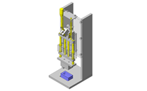
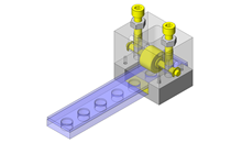
No.000237 Cylindrical Sheet Heat Welding
13
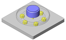
Retains workpiece using vacuum suction.
Relevant category


Cartridge Heaters

| Product name | Cartridge Heaters - Configurable Length/Power |
|---|---|
| Part number | MCHS12-400-V100-W400-F1000 |
Selection criteria
Selected as heating element.
Available sizes
■Cartridge Heaters - Configurable Length/Power
| Sheath Dia. | Material | |||
|---|---|---|---|---|
| Main Body | Lead Wire | Lead Wire Film | Terminal | |
| 3.1 | 304 Stainless Steel | Copper Wire | Glass Braid | - |
| 4 | Nickel | Glass Braid + Polyimide Film | - | |
| 5~18.95 | 321 Stainless Steel | Glass Braid | Copper + Tin Plating | |
■Sizes and Dimensions
| Sheath Dia. | Sheath length configurable in 1mm increments | Voltage (Selectable) | Electrical power configurable in 10W increments | Lead Wire Length 10mm increments |
|---|---|---|---|---|
| 6 | 50~250 | 100 | 50~500 | 100~1000 |
| 110 | 50~500 | |||
| 200 | 60~600 | |||
| 220 | 80~600 | |||
| 6.25 | 100 | 50~500 | ||
| 110 | 50~500 | |||
| 200 | 60~600 | |||
| 220 | 80~600 | |||
| 8 | 50~400 | 100 | 50~600 | |
| 110 | 50~600 | |||
| 200 | 50~1200 | |||
| 220 | 70~1200 | |||
| 9.42 | 100 | 50~600 | ||
| 110 | 50~600 | |||
| 200 | 50~1200 | |||
| 220 | 70~1200 | |||
| 10 | 50~800 | 100 | 50~600 | |
| 110 | 50~600 | |||
| 200 | 50~1200 | |||
| 220 | 70~1200 | |||
| 12 | 100 | 50~800 | ||
| 110 | 50~800 | |||
| 200 | 50~1600 | |||
| 220 | 70~1600 | |||
| 12.6 | 100 | 50~800 | ||
| 110 | 50~800 | |||
| 200 | 50~1600 | |||
| 220 | 70~1600 | |||
| 14 | 100 | 50~800 | ||
| 110 | 50~800 | |||
| 200 | 60~1600 | |||
| 220 | 80~1600 | |||
| 15.77 | 100 | 50~800 | ||
| 110 | 60~800 | |||
| 200 | 70~1600 | |||
| 220 | 90~1600 | |||
| 16 | 100 | 50~800 | ||
| 110 | 60~800 | |||
| 200 | 70~1600 | |||
| 220 | 90~1600 | |||
| 18 | 100 | 50~800 | ||
| 110 | 60~800 | |||
| 200 | 100~1600 | |||
| 220 | 130~1600 | |||
| 18.95 | 100 | 50~800 | ||
| 110 | 60~800 | |||
| 200 | 100~1600 | |||
| 220 | 130~1600 |

Angular Contact Bearings with Housings

| Product name | Angular Contact Bearings with Housings - Back-to-Back Combination + Deep Groove Ball Bearing, with Pilot |
|---|---|
| Part number | ABGY7006-N-120 |
| Features | Angular Contact Bearings with Housings - Back-to-Back Combination + Deep Groove Ball Bearing, with Pilot |
Selection criteria
Select a highly durable angular bearing in case an external force is applied when mounting or removing the work piece.
Available sizes
■Angular Contact Bearings with Housings - Back-to-Back Combination + Deep Groove Ball Bearing, with Pilot
| (1) Angular Contact Bearings (Back-to-Back Combination) | (3) Holder, (4) Inner Ring Spacer, (5) Standard Cover, (6) Standard Cover, Oil Seal Cover, or O-Ring Cover, (7) Inner Ring Collar | (8) Cover Mounting Screw | ||
|---|---|---|---|---|
| (2) Deep Groove Ball Bearings | ||||
| Material | Material | Surface Treatment | Material | Surface Treatment |
| 52100 Bearing Steel | 1045 Carbon Steel | Black Oxide | 4137 Alloy Steel | Black Oxide |
| Electroless Nickel Plating | 304 Stainless Steel | - | ||
■Sizes and Dimensions
| Bearing No. | Cover Selection | Overall Length | |
|---|---|---|---|
| 7002 | Standard Oil Seal For O-Ring | 60 | 75 |
| 7003 | 70 | 85 | |
| 7004 | 80 | 100 | |
| 7005 | 100 | 125 | |
| 7006 | 120 | 150 | |
| 7007 | 140 | 175 | |
| 7008 | 160 | 200 | |
| 7009 | 180 | 225 | |
| 7010 | 200 | 250 | |

Indexing Plungers

| Product name | Indexing Plungers- Fine Thread, Return Type |
|---|---|
| Part number | PXYK10 |
Selection criteria
Used to temporarily position the work piece during operation.
Available sizes
■Indexing Plungers- Fine Thread, Return Type
| Knob | Main Body | Pin | Spring | Lock Nut | |||
|---|---|---|---|---|---|---|---|
| Material | Material | Surface Treatment | Material | Hardness | Surface Treatment | Material | |
| Nylon 6 (Mat Black) | 1213 Carbon Steel | Black Oxide | 1045 Carbon Steel | 50-60HRC | Black Oxide | Spring Steel | Not Provided |
| Provided | |||||||
| 303 Stainless Steel | - | 303 Stainless Steel | - | Nickel Plating | 301 Stainless Steel | Not Provided | |
| Provided | |||||||
■Sizes and Dimensions
| Thread Dia. X Pitch (Fine thread) | Knob O.D. | Pin Dia. | Stroke | Overall Length | Thread Length |
|---|---|---|---|---|---|
| M10×1.0 | φ21 | φ13.8 | 5 | 45 | 17 |
| 51 | |||||
| M12×1.5 | φ25 | φ16.2 | 6 | 54.5 | 20 |
| 61 | |||||
| M16×1.5 | φ31 | φ21.9 | 7 | 69 | 26 |
| 75.5 |
Performance info.
■Spring Constants of Indexing Plungers (Fine thread)
| Thread Dia. | Stroke | Load(N) | |
|---|---|---|---|
| Min. | Max. | ||
| M10 | 5 | 7 | 17 |
| M12 | 6 | 9 | 24 |
| M16 | 8 | 11 | 30 |


-
 TERMS AND CONDITIONS FOR USE OF CAD DATA
-
Your access to the CAD data that MISUMI Corporation (hereinafter referred to as the Company) posts on this site (including 3D CAD data, intermediate 3D CAD data and 2D CAD data; hereinafter referred to as the Data) are of products manufactured and/or sold by the Company (hereinafter referred to as the Products) assumes that you have read and accepted these terms and conditions which govern your use of the Data. If you do not agree to these terms and conditions, you must stop using this website and the Data. You must not use the Data for any unlawful purpose or in any manner inconsistent with these terms and conditions.
- 1. CAD Data
- The Data is prepared for assisting the Company's users in the CAD design process by providing dimensions and other Product information. In order to provide the best speed and stability working within this site, the Product drawings were simplified to reduce the size of the Data. For instance, some of the Products are shown without the oil groove shape, screws or spring shape. Also, please be aware that the tolerance, surface roughness and/or chamfer of the Data may vary from the actual Products.
- 2. Disclaimer on Data
- While the Company has carefully prepared the Data, accuracy of the Data is not guaranteed and is subject to the variances as described above. The Company may also modify, add or delete the Data at any time without prior notice. The Company assumes no liability for any direct, indirect, consequential or special damages that you may claim resulted from your use of the Data or any changes to or deletions of the Data regardless of the reason. The Company provides no warranty as to the quality, accuracy, functionality, safety or reliability of the combination of Products and parts. Example applications and combinations of the Products are provided for illustrative purposes only.
- 3. Copyright
-
Copyrights to the content and the Data belong to the Company or the manufacturers of the Products. The said copyright is protected by the Copyright Act and international treaties. The use (including duplication, modification, uploading, posting, transmission, distribution, licensing, sales and publishing) of the Data except for the purpose to use the Data described above without prior approval of the Company is not allowed. The Data cannot be used for any purposes (including sales promotion) except for designing your machine. If you violate this provision or the laws or regulations, the Company may prohibit you from the use of the Data, the Company’s site and/or take legal action. So long as you comply with these terms and conditions, the Company grants to you a non-exclusive, non-transferable, revocable license to access and use the Data for the sole purpose of assisting you in designing machines that incorporate products.
In case that the CAD data is found to have been to be used for any purpose other than mentioned above or against the related laws, MISUMI may take legal actions, including the one for blocking the involved user from using CAD data and from accessing to the MISUMI site. - 4. Disclaimer of Warranty
- ANY AND ALL CONTENT APPEARING ON THIS WEB SITE IS PROVIDED FOR INFORMATIONAL PURPOSES ONLY. THIS WEB SITE, ITS CONTENT AND ITS LINKS ARE PROVIDED ON AN "AS IS" AND "AS AVAILABLE" BASIS AND ARE USED ONLY AT YOUR SOLE RISK, TO THE FULLEST EXTENT PERMISSIBLE BY LAW. THE COMPANY DISCLAIMS ALL WARRANTIES, EXPRESS OR IMPLIED, OF ANY KIND, REGARDING THIS WEB SITE (INCLUDING ITS CONTENT, HARDWARE, SOFTWARE AND LINKS), INCLUDING AS TO FITNESS FOR A PARTICULAR PURPOSE, MERCHANTABILITY, TITLE, NON INFRINGEMENT, RESULTS, ACCURACY, COMPLETENESS, ACCESSIBILITY, COMPATIBILITY, SECURITY AND FREEDOM FROM COMPUTER VIRUS. THE COMPANY WILL NOT BE LIABLE FOR ANY DAMAGES OR LOSSES, INCLUDING DIRECT, INDIRECT, CONSEQUENTIAL, SPECIAL, INCIDENTAL OR PUNITIVE DAMAGES AND/OR LOST PROFITS, IN CONNECTION WITH USE OF THE INTERNET, THIS WEB SITE, ITS CONTENT OR ITS LINKS
Further, the Company will not be liable to you for any failure or delay by the Company to provide access to the Data or any of its obligations under these terms and conditions where such failure or delay is the direct or indirect result of any circumstances beyond the Company's reasonable control (and the Company's obligations will be suspended for the duration of such circumstances).
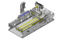
CAD Download (Unit Assembly)
CAD Download: File Format
CAD Data Limitations
-
Assembly data shows the assembly drawings in the concept design phase. The sole purpose of the data is to explain the structure and functionality of the assembly and is not considered nor to be used as a final design.
You will need to edit the Data so that it meets your specific design conditions. -
Unit assembly Data consists of some sub-assemblies.
It is configured so that each sub-assembly unit can be used as it is or edited. - The Data for fabricated parts is based on easy-to-edit dimensions and shapes in sketches and histories.
- The Data including the third-part components are made by the Company.
* The part in the frame is a sub-assembly unit.
-
Your access to the CAD data that MISUMI Corporation (hereinafter referred to as the Company) posts on this site (including 3D CAD data, intermediate 3D CAD data and 2D CAD data; hereinafter referred to as the Data) are of products manufactured and/or sold by the Company (hereinafter referred to as the Products) assumes that you have read and accepted these terms and conditions which govern your use of the Data. If you do not agree to these terms and conditions, you must stop using this website and the Data. You must not use the Data for any unlawful purpose or in any manner inconsistent with these terms and conditions.
-

- * Unit assembly Data consists of some sub-assemblies.
It is configured so that each sub-assembly unit can be used as it is or edited.
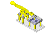
Application Overview
Purpose
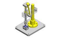
- A device designed to hold a resin sheet in a cylindrical shape while the overlapping portions are being heat welded together.
- Welding unit only advances from protective cover when buttons on each side of the unit are pressed simultaneously.
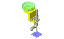
- An indexing plunger is used to fix the rotary table into position.
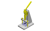
Points for use
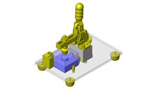
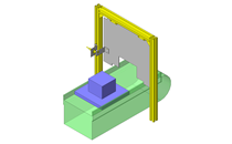
- The resin work piece is placed manually.
- Once workpiece is in position, the indexing plunger rotates the workpiece into welding position.
- After the welding mechanism unit is retracted, the workpiece is removed from the top.
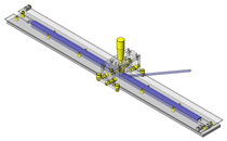
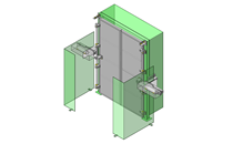
- To prevent malfunctions and enhance safety, an area sensor is installed. Another safety measure is the welding unit will not emerge or heat until two buttons outside the workspace are pressed.
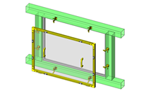
Target workpiece
- Resin sheet
- Outer dimensions: W335 x D405 x t0.1mm
- Weight: 18g
Design Specifications
Operating Conditions or Design Requirements
- Air cylinder stroke amount: 100mm
<Maximum stroke amount: 100mm> - Outer dimensions
W650xD675xH658mm
Required Performance
- Cylinder thrust: 11.8N or higher
Selection Criteria for Main Components
- Air cylinder
- A compact cylinder is selected to save space.
- Cartridge Heaters
- A long cartridge heater that satisfies the heat quantity requirement for heat welding is selected.
Design Evaluation
Verification of main components
- Cylindrical thrust is verified based on the workpiece load and the heat quantity required of the heater is verified based on the heating conditions.
- Cylinder
- Conditional value: mass to move: m = 4kg, friction coefficient μ = 0.3, load factor η = 0.5 (from catalog), outstroke pressure area A1 = 1256mm² (from catalog), operating pressure P = 0.4MPa
- Load applied to cylinder: F = mgμ, hence, F = 4 x 9.8 x 0.3 = 11.8N,
- Cylinder output F1 = load factor x outstroke pressure area x operating pressure, hence, F1 = 0.5 x 1256 x 0.4 = 251.2N
-> Safety factor: F1/F = 251.2/11.8 ≈ 21
- Heat quantity required of the heater
- Conditional value: mass of heated workpiece: 0.585kg (A5052), specific heat of heated workpiece: 0.23kcal/kg°C, temperature rise: 190°C (heating until the temperature of heated workpiece reaches 210°C), heating time: 0.25h (idling), heating time: approx. 3 sec (workpiece), efficiency: 0.3 (standard specification: from catalog)
- The workpiece heating time should be determined through trial and error because it depends on the size, thickness, and material of the workpiece.
- Heat quantity required of heater H (kw) = mass of heated workpiece (kg) x specific heat of heated workpiece (kcal/kg°C) x temperature rise (°C)/(860 x heating time (h) x efficiency (η)), hence
H = 0.585 x 0.23 x 190/(860 x 0.25 x 0.3) = 0.396kW = 396W
Other Design Consideration
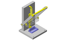
- For safety the heater is inside the cover except during welding.
- To prevent injuries, the buttons to operate the heating element are placed outside the work space.
- During work piece placement, wrap the work piece on revolution along the groves of the suction block, confirm the overlap is 5mm, and then manually rotate the suction block to the welding the position and fix into place with the plunger.
- The material and shape of the welding portion are determined through trial and error. Each work piece will be different and depends of the material, thickness, and shape.
Explore Similar Application Examples

-

-

-
-

-

-

-
-

-
-

-

-
-

-
-

-

-
-
Relevant category
-
-
-

-

-

-
-
-
-

-

-

-

-

-
-

-

-
-

-

-

Payment Methods
- Credit Card
-
- Bank
-
- Prompt Pay
-


Social Media
MISUMI Contact
Copyright © MISUMI Corporation All Rights Reserved.