(!) Since support from Microsoft will end on January 14 2020, Windows 7 user might not be able to use MISUMI website effectively. Please consider to update your system as ‘MISUMI Website system requirement’.


- inCAD Library Home
- > No.000177 Reverse Gripper
No.000177 Reverse Gripper
54
Gripper that can reverse and rotate.
Relevant category


Cable Carriers

| Product name | Cable Carriers -Slit- |
|---|---|
| Part number | SE08F-30-028-14 |
Selection criteria
Organizes cables and protects them against wear and tear on moving objects.
Available sizes
■Cable Carriers - Slit (Type 08F)
| Type | Material |
|---|---|
| Outer Radius Mount | Special Plastic (Operating Temperature: -30 - 100℃) Equivalent to Flammability Standard UL94-V2 |
| Inner Radius Mount |
■Sizes and Overall Dimensions
| Bending Radius | Number of Links | Mounting height | (Required Space Height) | (Arc + Allowance) | Link Pitch |
|---|---|---|---|---|---|
| 28 | 1〜37 | 76 | 91 | 130 | 20 |
| 38 | 1〜38 | 96 | 111 | 160 | |
| 48 | 1〜40 | 116 | 131 | 190 |
■Sizes and Link Cross Section Dimensions
| Inner height | Overall Height | Inner width | Overall Width | Number of Comb Teeth |
|---|---|---|---|---|
| 14.6 | 19.3 | 16 | 24.2 | 2 |
| 20 | 28.2 | 2 | ||
| 30 | 38.2 | 3 | ||
| 40 | 48.2 | 4 | ||
| 50 | 58.2 | 5 |

Bearings with Housings
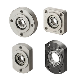
| Product name | Bearings with Housings - Direct Mount, Standard with Pilot, Retained |
|---|---|
| Part number | SBGCR6901ZZ |
Selection criteria
Bearing and housing sold as a set.
Available sizes
■Bearings with Housings, Pilot, Retained
| Flange Shape | Material | Surface Treatment | Material of the Included Retaining Ring | |
|---|---|---|---|---|
| Bearing | Holder | Holder | ||
| Round ・ Square ・ Compact | Steel | 1045 Carbon Steel | Black Oxide | Spring Steel |
| Electroless Nickel Plating | 304 Stainless Steel | |||
| 2017 Aluminum Alloy | Clear Anodize | |||
| Stainless Steel | ||||
| 304 Stainless Steel | − | |||
■Sizes and Dimensions
| Seal | Bearing | Shaft Bore Dia. | Bearing O.D. | Bearing Width | Flange External Dimensions | Compact Flange Wrench Flats | Overall Thickness | Flange Thickness | Pilot Part Length | Pilot Dia. |
|---|---|---|---|---|---|---|---|---|---|---|
| Non-contact Rubber Seal ・ Contact Rubber Seal | 623 | φ3 | φ10 | 4 | 33 | 16 | 9 | 7 | 2 | φ14 |
| 624 | φ4 | φ13 | 5 | 35 | 18 | 10 | 8 | φ17 | ||
| 605 | φ5 | φ14 | 5 | 36 | 20 | 10 | 8 | φ18 | ||
| 625 | φ16 | 5 | 38 | 22 | 10 | 8 | φ20 | |||
| 606 | φ6 | φ17 | 6 | 39 | 23 | 11 | 9 | φ21 | ||
| 626 | φ19 | 6 | 41 | 25 | 11 | 9 | φ24 | |||
| 698 | φ8 | φ19 | 6 | 41 | 25 | 11 | 9 | φ24 | ||
| 608 | φ22 | 7 | 45 | 29 | 12 | 10 | φ27 | |||
| 628 | φ24 | 8 | 47 | 32 | 13 | 11 | φ30 | |||
| 6800 | φ10 | φ19 | 5 | 41 | 25 | 10 | 8 | φ24 | ||
| 6900 | φ22 | 6 | 45 | 29 | 11 | 9 | φ27 | |||
| 6000 | φ26 | 8 | 50 | 34 | 13 | 11 | φ32 | |||
| 6200 | φ30 | 9 | 54 | 38 | 14 | 12 | φ36 | |||
| 6801 | φ12 | φ21 | 5 | 44 | 29 | 10 | 8 | φ26 | ||
| 6901 | φ24 | 6 | 48 | 31 | 11 | 9 | φ30 | |||
| 6001 | φ28 | 8 | 52 | 36 | 13 | 11 | φ34 | |||
| 6201 | 32φ | 10 | 56 | 40 | 15 | 13 | φ38 | |||
| 6802 | φ15 | φ24 | 5 | 47 | 32 | 10 | 8 | φ30 | ||
| 6902 | φ28 | 7 | 57 | 37 | 12 | 10 | φ35 | |||
| 6002 | φ32 | 9 | 60 | 40 | 14 | 12 | φ38 | |||
| 6202 | φ35 | 11 | 64 | 44 | 17 | 15 | φ42 | |||
| 6903 | φ17 | φ30 | 7 | 60 | 38 | 12 | 10 | φ36 | ||
| 6003 | φ35 | 10 | 66 | 44 | 16 | 14 | φ42 | |||
| 6203 | φ40 | 12 | 72 | 50 | 18 | 16 | φ48 | |||
| 6804 | φ20 | φ32 | 7 | 60 | 40 | 12 | 10 | φ38 | ||
| 6904 | φ37 | 9 | 69 | 47 | 15 | 13 | φ45 | |||
| 6004 | φ42 | 12 | 77 | 54 | 18 | 16 | φ50 | |||
| 6204 | φ47 | 14 | 81 | 58 | 20 | 18 | φ54 | |||
| 6805 | φ25 | φ37 | 7 | 69 | 47 | 13 | 11 | φ45 | ||
| 6905 | φ42 | 9 | 77 | 54 | 15 | 13 | φ50 | |||
| 6005 | φ47 | 12 | 88 | 58 | 18 | 16 | φ54 | |||
| 6205 | φ52 | 15 | 94 | 64 | 22 | 20 | φ60 | |||
| 6806 | φ30 | φ42 | 7 | 77 | 54 | 13 | 11 | φ50 | ||
| 6906 | φ47 | 9 | 88 | 58 | 15 | 13 | φ54 | |||
| 6006 | φ55 | 13 | 96 | 66 | 20 | 18 | φ62 | |||
| 6206 | φ62 | 16 | 104 | 74 | 23 | 21 | φ70 | |||
| 6007 | φ35 | 14 | 21 | 19 | ||||||
| 6207 | φ72 | 17 | 126 | 88 | 26 | 23 | 3 | φ84 | ||
| 6008 | φ40 | φ68 | 15 | 114 | 82 | 23 | 21 | 2 | φ78 | |
| 6208 | φ80 | 18 | 134 | 96 | 27 | 24 | 3 | φ92 | ||
| Double shielded | 6010 | φ50 | 16 | 25 | 22 | |||||
| 6210 | φ90 | 20 | 147 | 110 | 31 | 28 | φ106 |
Accuracy Info
■Accuracy Information of the Bearings with Housings, Pilot, Retained
Pilot Dia. Tolerance: g7
Concentricity of the Pilot and the Bearing Housing: 0.02 or less
Perpendicularity of the Flange Mounting Surface and the Bearing Housing: 0.01 or less

Shaft Collar
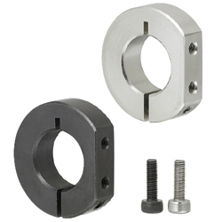
| Product name | Shaft Collars - D Shaped - Compact Slit Type |
|---|---|
| Part number | PSDNJ15-8 |
| Features | Utilization of Mounting Hole on Cut Side facilitates Sensor Bracket Mounting |
Selection criteria
Mounting holes on side allow for easy installation of sensor brackets.
Available sizes
■Shaft Collar Clamp D Cut, Cut Surface Mount Hole, Compact
| Material | Surface Treatment | Accessory |
|---|---|---|
| 1045 Carbon Steel | Black Oxide | Hex Socket Head Cap Screw 1 pcs. |
| Electroless Nickel Plating | Hex Socket Head Cap Screw 1 pcs. (SUS) | |
| 304 Stainless Steel | − |
■Sizes and Dimensions
| Shaft Bore Dia. | Overall Width (Thickness) | O.D. | Fastening Screw Dia. (Coarse) | Mounting Screw Dia. (Coarse) |
|---|---|---|---|---|
| φ10 | 8 | φ30 | M3 | M3 |
| φ12 | ||||
| φ15 | ||||
| φ16 | ||||
| φ20 | φ35 | |||
| φ25 | 10 | φ42 | M4 | M4 |
| φ30 | 12 | φ50 | M5 |
* Please see the product pages for dimension details.
Accuracy Info
Shaft Bore Dia. Tolerance: +0.05/+0.01
O.D. Tolerance: ±0.1
Overall Width Tolerance: ±0.1


-

-
 TERMS AND CONDITIONS FOR USE OF CAD DATA
-
Your access to the CAD data that MISUMI Corporation (hereinafter referred to as the Company) posts on this site (including 3D CAD data, intermediate 3D CAD data and 2D CAD data; hereinafter referred to as the Data) are of products manufactured and/or sold by the Company (hereinafter referred to as the Products) assumes that you have read and accepted these terms and conditions which govern your use of the Data. If you do not agree to these terms and conditions, you must stop using this website and the Data. You must not use the Data for any unlawful purpose or in any manner inconsistent with these terms and conditions.
- 1. CAD Data
- The Data is prepared for assisting the Company's users in the CAD design process by providing dimensions and other Product information. In order to provide the best speed and stability working within this site, the Product drawings were simplified to reduce the size of the Data. For instance, some of the Products are shown without the oil groove shape, screws or spring shape. Also, please be aware that the tolerance, surface roughness and/or chamfer of the Data may vary from the actual Products.
- 2. Disclaimer on Data
- While the Company has carefully prepared the Data, accuracy of the Data is not guaranteed and is subject to the variances as described above. The Company may also modify, add or delete the Data at any time without prior notice. The Company assumes no liability for any direct, indirect, consequential or special damages that you may claim resulted from your use of the Data or any changes to or deletions of the Data regardless of the reason. The Company provides no warranty as to the quality, accuracy, functionality, safety or reliability of the combination of Products and parts. Example applications and combinations of the Products are provided for illustrative purposes only.
- 3. Copyright
-
Copyrights to the content and the Data belong to the Company or the manufacturers of the Products. The said copyright is protected by the Copyright Act and international treaties. The use (including duplication, modification, uploading, posting, transmission, distribution, licensing, sales and publishing) of the Data except for the purpose to use the Data described above without prior approval of the Company is not allowed. The Data cannot be used for any purposes (including sales promotion) except for designing your machine. If you violate this provision or the laws or regulations, the Company may prohibit you from the use of the Data, the Company’s site and/or take legal action. So long as you comply with these terms and conditions, the Company grants to you a non-exclusive, non-transferable, revocable license to access and use the Data for the sole purpose of assisting you in designing machines that incorporate products.
In case that the CAD data is found to have been to be used for any purpose other than mentioned above or against the related laws, MISUMI may take legal actions, including the one for blocking the involved user from using CAD data and from accessing to the MISUMI site. - 4. Disclaimer of Warranty
- ANY AND ALL CONTENT APPEARING ON THIS WEB SITE IS PROVIDED FOR INFORMATIONAL PURPOSES ONLY. THIS WEB SITE, ITS CONTENT AND ITS LINKS ARE PROVIDED ON AN "AS IS" AND "AS AVAILABLE" BASIS AND ARE USED ONLY AT YOUR SOLE RISK, TO THE FULLEST EXTENT PERMISSIBLE BY LAW. THE COMPANY DISCLAIMS ALL WARRANTIES, EXPRESS OR IMPLIED, OF ANY KIND, REGARDING THIS WEB SITE (INCLUDING ITS CONTENT, HARDWARE, SOFTWARE AND LINKS), INCLUDING AS TO FITNESS FOR A PARTICULAR PURPOSE, MERCHANTABILITY, TITLE, NON INFRINGEMENT, RESULTS, ACCURACY, COMPLETENESS, ACCESSIBILITY, COMPATIBILITY, SECURITY AND FREEDOM FROM COMPUTER VIRUS. THE COMPANY WILL NOT BE LIABLE FOR ANY DAMAGES OR LOSSES, INCLUDING DIRECT, INDIRECT, CONSEQUENTIAL, SPECIAL, INCIDENTAL OR PUNITIVE DAMAGES AND/OR LOST PROFITS, IN CONNECTION WITH USE OF THE INTERNET, THIS WEB SITE, ITS CONTENT OR ITS LINKS
Further, the Company will not be liable to you for any failure or delay by the Company to provide access to the Data or any of its obligations under these terms and conditions where such failure or delay is the direct or indirect result of any circumstances beyond the Company's reasonable control (and the Company's obligations will be suspended for the duration of such circumstances).
CAD Download (Unit Assembly)
CAD Download: File Format
CAD Data Limitations
-
Assembly data shows the assembly drawings in the concept design phase. The sole purpose of the data is to explain the structure and functionality of the assembly and is not considered nor to be used as a final design.
You will need to edit the Data so that it meets your specific design conditions. -
Unit assembly Data consists of some sub-assemblies.
It is configured so that each sub-assembly unit can be used as it is or edited. - The Data for fabricated parts is based on easy-to-edit dimensions and shapes in sketches and histories.
- The Data including the third-part components are made by the Company.
* The part in the frame is a sub-assembly unit.
-
Your access to the CAD data that MISUMI Corporation (hereinafter referred to as the Company) posts on this site (including 3D CAD data, intermediate 3D CAD data and 2D CAD data; hereinafter referred to as the Data) are of products manufactured and/or sold by the Company (hereinafter referred to as the Products) assumes that you have read and accepted these terms and conditions which govern your use of the Data. If you do not agree to these terms and conditions, you must stop using this website and the Data. You must not use the Data for any unlawful purpose or in any manner inconsistent with these terms and conditions.
-

- * Unit assembly Data consists of some sub-assemblies.
It is configured so that each sub-assembly unit can be used as it is or edited.
Application Overview
Purpose
- Purpose
- Gripper reverses and rotates the workpiece as it is laser engraved.
- Operation
- Workpieces are transported to the receiving/discharging position by a robot. Once the workpiece is in place, the three-claw pneumatic gripper reverses the part 90° and moves forward into printing position. As the piece is being laser marked, a stepper motor and timing belt rotates the workpiece. When printing is completed, the gripper reverses back 90° into receiving/discharging position and the piece is removed by a robot.
Target workpiece
- Shape: Bar-shape
- Workpiece size: φ 12 x L 145 mm
- Weight: 37 g
Design Specifications
Operating Conditions or Design Requirements
- Stroke of the three-claw pneumatic gripper: 6 mm
- Reversing angle: 90°
- Rotation angle: 90°
- External size: W 460 x D 165 x H 230 mm
Required Performance
- Position repeatability accuracy of the three-claw pneumatic gripper: ± 0.1 mm
Design Evaluation
Verification of main components
- Verify the gripping force of the pneumatic gripper for appropriate workpiece gripping force.
- Check the gripping force of the three-claw pneumatic gripper
- Conditional values: Center of gravity of workpiece L1 = 85mm, workpiece gripping point L2 = 59.5 mm, workpiece weight m = 37 g, supply pressure p = 0.5MPa, gravitational acceleration g = 9.8m/s², friction coefficient μ=0.2 (metal vs. metal)
- Gripping force F1 of the three-claw pneumatic gripper at supply pressure p, and workpiece gripping point L2 is obtained form the graph as F1 = 4.5 N.
Gripping force on the workpiece F1' = F1 x μ Thus, F1' = 4.5 x 0.2 = 0.9 N - Required gripping force F2 is obtained from the balance of the moment as follows.
Mg×L1=F2×L2
F2 = Mg x (L1/L2) Thus, F2 = 37 x 10⁻³ x 9.8 x (85/59.5) = 0.518 N
F1'>F2 Thus, sufficient gripping force is achieved.
Other Design Consideration
- Install a mechanical stopper to limit the rotation of the three-claw pneumatic gripper below 270°. This stopper serves as a countermeasure against cable entanglement and disconnection.
- For safety purposes, a cover is installed over the timing belt.
Explore Similar Application Examples

-

-

-

-

-

-

-

-

-

-

-

-

-

-

-

-

-

-

-

Relevant category
-

-

-

-

-

-

-

-

-

-

-

-

-

-

-

-

-

-

-

-

-

-

-

-

-

-

-

-

-

-

-

-

-

-

-

-

-

-

Relevant category
-

-

-

-

-

-

-

-

-

-

-

-

-

-

-

-

-

-

-

-

-

-

-

-

-

-

-

-

-

-

-

-

-

-

-

-

-

-

-

-

-

-

-

-

-

-

-

-

-

-

-

-

-

-

-

-

-

-

-

-

-

-

-

-

-

-


Payment Methods
- Credit Card
-
- Bank
-
- Prompt Pay
-


Social Media
MISUMI Contact
Copyright © MISUMI Corporation All Rights Reserved.