(!) Since support from Microsoft will end on January 14 2020, Windows 7 user might not be able to use MISUMI website effectively. Please consider to update your system as ‘MISUMI Website system requirement’.


- inCAD Library Home
- > No.000018 Test Fixture for Product Aging
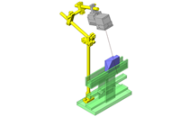
No.000018 Test Fixture for Product Aging
35
35
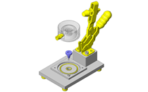
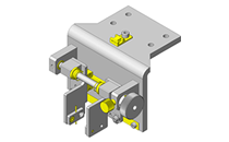
Mechanism to convert rotary motion to reciprocating motion
Relevant category


Pivot Pin

| Product name | Precision Pivot Pins - Flanged, Hex Socket Head, Threaded with Lock Nut |
|---|---|
| Part number | SCLBR8-17-FC4-MC4 |
* Orange colored cells in the table below indicate the part numbers used in this example.
Selection criteria
To support motor arm rotation.
Available sizes
Precision Pivot Pins - Flanged, Hex Socket Head, Threaded with Lock Nut
| Material | Hardness | Surface treatment | Included nut material | |
|---|---|---|---|---|
| Standard nut | U nut | |||
| 1045 Carbon Steel | − | Black oxide | SWRCH Carbon Steel | 1018 Carbon Steel |
| 40〜45HRC | ||||
| − | Electroless nickel plating | 304 Stainless Steel | 304 Stainless Steel | |
| 40〜45HRC | ||||
| Plating hardness 750HV~ | Hard chrome plating | SWRM Low Carbon Steel | 1018 Carbon Steel | |
| Plating thickness 3μm or more | ||||
| 304 Stainless Steel | − | − | 304 Stainless Steel | 304 Stainless Steel |
| 440C Stainless Steel | 45〜50HRC | |||
| 45〜50HRC | Hard chrome plating | |||
| Plating hardness 750HV~ | Plating thickness 3μm or more | |||
■Sizes and Dimensions
| Pin DIA. | Pin section length | Head O.D. | Head height | Threaded section length | Screw DIA. X Pitch |
|---|---|---|---|---|---|
| (Configure in 0.1mm increments) | |||||
| φ4 | 10.0〜 50.0 | φ7 | 5 | 6 | M 3×0.5 |
| φ5 | 10.0〜 60.0 | φ9 | M 4×0.7 | ||
| φ6 | 10.0〜100.0 | φ10 | 9 | M 5×0.8 | |
| φ8 | 10.0〜100.0 | φ13 | M 6×1.0 | ||
| φ10 | φ16 | 12 | M 8×1.25 | ||
| φ12 | 10.0〜200.0 | φ18 | 16 | M10×1.5 | |
| φ13 | 20.0〜200.0 | φ24 | 18 | M12×1.75 | |
| φ14 | |||||
| φ15 | |||||
| φ16 | 20.0〜200.0 | ||||
| φ17 | |||||
| φ18 | 24 | ||||
| φ20 | φ27 | M16×2.0 | |||
| φ22 | 20.0〜200.0 | ||||
| φ25 | φ30 |
Accuracy Info
Pivot pin, Flanged with Hex socket with a nut: Pin O.D. tolerance (g6)
| Pin diameter | Tolerance |
|---|---|
| φ4 | -0.004/-0.012 |
| φ5 | |
| φ6 | |
| φ8 | -0.005/-0.014 |
| φ10 | |
| φ12 | -0.006/-0.017 |
| φ13 | |
| φ14 | |
| φ15 | |
| φ16 | |
| φ17 | |
| φ18 | |
| φ20 | -0.007/-0.020 |
| φ22 | |
| φ25 |

Tension Spring
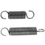
| Product name | Tension Springs -Heavy Load- |
|---|---|
| Part number | AWF12-60 |
* Orange colored cells in the table below indicate the part numbers used in this example.
Selection criteria
To support applied load to workpiece.
Available sizes
Tension Springs -Heavy Load-
| Load class | Material | O.D. | Free length | End hooks | ||
|---|---|---|---|---|---|---|
| Spring Steel (ASTM A228) | 304 Stainless Steel | Range | Range | S hook | 90 deg. S hook | |
| Extra light load | ○ | ○ | φ2 - 12 | 10 - 100 | ○ | - |
| Light load | ○ | △ | φ2 - 20 | 10 - 175 | ○ | △ |
| Light-Med. load | ○ | △ | φ2 - 20 | 10 - 175 | ○ | △ |
| Med. load | ○ | △ | φ2 - 24 | 10 - 200 | ○ | △ |
| Med.-Heavy load | ○ | - | φ2 - 12 | 10 - 100 | ○ | - |
| Heavy load | ○ | △ | φ3 - 24 | 10 - 200 | ○ | △ |
Performance info.
Load info. on tension springs
| Load class | Ref. Load (N) | |
|---|---|---|
| Min. | Max. | |
| Extra light load | 0.69 | 19.6 |
| Light load | 1.86 | 78.45 |
| Light-Med. load | 2.45 | 98.07 |
| Med. load | 3.53 | 225.55 |
| Med.-Heavy load | 6.47 | 83.36 |
| Heavy load | 8.8 | 430.51 |
Technical calculations
Load info. on tension springs
P = Pi + (k x F)
- P: Load (N)
- Pi: Initial tension (N)
- k: Spring constant(N/mm)
- F: Deflection (mm)


-
 TERMS AND CONDITIONS FOR USE OF CAD DATA
-
Your access to the CAD data that MISUMI Corporation (hereinafter referred to as the Company) posts on this site (including 3D CAD data, intermediate 3D CAD data and 2D CAD data; hereinafter referred to as the Data) are of products manufactured and/or sold by the Company (hereinafter referred to as the Products) assumes that you have read and accepted these terms and conditions which govern your use of the Data. If you do not agree to these terms and conditions, you must stop using this website and the Data. You must not use the Data for any unlawful purpose or in any manner inconsistent with these terms and conditions.
- 1. CAD Data
- The Data is prepared for assisting the Company's users in the CAD design process by providing dimensions and other Product information. In order to provide the best speed and stability working within this site, the Product drawings were simplified to reduce the size of the Data. For instance, some of the Products are shown without the oil groove shape, screws or spring shape. Also, please be aware that the tolerance, surface roughness and/or chamfer of the Data may vary from the actual Products.
- 2. Disclaimer on Data
- While the Company has carefully prepared the Data, accuracy of the Data is not guaranteed and is subject to the variances as described above. The Company may also modify, add or delete the Data at any time without prior notice. The Company assumes no liability for any direct, indirect, consequential or special damages that you may claim resulted from your use of the Data or any changes to or deletions of the Data regardless of the reason. The Company provides no warranty as to the quality, accuracy, functionality, safety or reliability of the combination of Products and parts. Example applications and combinations of the Products are provided for illustrative purposes only.
- 3. Copyright
-
Copyrights to the content and the Data belong to the Company or the manufacturers of the Products. The said copyright is protected by the Copyright Act and international treaties. The use (including duplication, modification, uploading, posting, transmission, distribution, licensing, sales and publishing) of the Data except for the purpose to use the Data described above without prior approval of the Company is not allowed. The Data cannot be used for any purposes (including sales promotion) except for designing your machine. If you violate this provision or the laws or regulations, the Company may prohibit you from the use of the Data, the Company’s site and/or take legal action. So long as you comply with these terms and conditions, the Company grants to you a non-exclusive, non-transferable, revocable license to access and use the Data for the sole purpose of assisting you in designing machines that incorporate products.
In case that the CAD data is found to have been to be used for any purpose other than mentioned above or against the related laws, MISUMI may take legal actions, including the one for blocking the involved user from using CAD data and from accessing to the MISUMI site. - 4. Disclaimer of Warranty
- ANY AND ALL CONTENT APPEARING ON THIS WEB SITE IS PROVIDED FOR INFORMATIONAL PURPOSES ONLY. THIS WEB SITE, ITS CONTENT AND ITS LINKS ARE PROVIDED ON AN "AS IS" AND "AS AVAILABLE" BASIS AND ARE USED ONLY AT YOUR SOLE RISK, TO THE FULLEST EXTENT PERMISSIBLE BY LAW. THE COMPANY DISCLAIMS ALL WARRANTIES, EXPRESS OR IMPLIED, OF ANY KIND, REGARDING THIS WEB SITE (INCLUDING ITS CONTENT, HARDWARE, SOFTWARE AND LINKS), INCLUDING AS TO FITNESS FOR A PARTICULAR PURPOSE, MERCHANTABILITY, TITLE, NON INFRINGEMENT, RESULTS, ACCURACY, COMPLETENESS, ACCESSIBILITY, COMPATIBILITY, SECURITY AND FREEDOM FROM COMPUTER VIRUS. THE COMPANY WILL NOT BE LIABLE FOR ANY DAMAGES OR LOSSES, INCLUDING DIRECT, INDIRECT, CONSEQUENTIAL, SPECIAL, INCIDENTAL OR PUNITIVE DAMAGES AND/OR LOST PROFITS, IN CONNECTION WITH USE OF THE INTERNET, THIS WEB SITE, ITS CONTENT OR ITS LINKS
Further, the Company will not be liable to you for any failure or delay by the Company to provide access to the Data or any of its obligations under these terms and conditions where such failure or delay is the direct or indirect result of any circumstances beyond the Company's reasonable control (and the Company's obligations will be suspended for the duration of such circumstances).
CAD Download (Unit Assembly)
CAD Download: File Format
CAD Data Limitations
-
Assembly data shows the assembly drawings in the concept design phase. The sole purpose of the data is to explain the structure and functionality of the assembly and is not considered nor to be used as a final design.
You will need to edit the Data so that it meets your specific design conditions. -
Unit assembly Data consists of some sub-assemblies.
It is configured so that each sub-assembly unit can be used as it is or edited. - The Data for fabricated parts is based on easy-to-edit dimensions and shapes in sketches and histories.
- The Data including the third-part components are made by the Company.
* The part in the frame is a sub-assembly unit.
-
Your access to the CAD data that MISUMI Corporation (hereinafter referred to as the Company) posts on this site (including 3D CAD data, intermediate 3D CAD data and 2D CAD data; hereinafter referred to as the Data) are of products manufactured and/or sold by the Company (hereinafter referred to as the Products) assumes that you have read and accepted these terms and conditions which govern your use of the Data. If you do not agree to these terms and conditions, you must stop using this website and the Data. You must not use the Data for any unlawful purpose or in any manner inconsistent with these terms and conditions.
-

- * Unit assembly Data consists of some sub-assemblies.
It is configured so that each sub-assembly unit can be used as it is or edited.
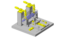
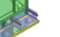
Application Overview
Purpose
- Fixture to measure aging variations (dimensional changes over time, and cracking, etc.) by applying repeated loads. (Not to the extent of destruction)
Points for use
- Oscillating mechanism driven by a motor.
Target workpiece
- Levered lug
External Dims.: W40 x D30 x H3 (excluding the lever)
Workpiece weight: 5g
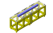
Design Specifications
Operating Conditions or Design Requirements
- Oscillates in ± 45° range.
- External dims.: W516 x D300 x H468
Required Performance
- Tensile load: 60N
Spring constant: 4.13N/mm
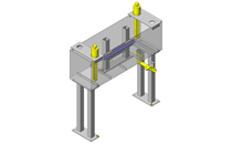
Selection Criteria for Main Components
- Motor
- A motor is selected for automated oscillating motion.
- Spring
- Spring selection makes applying arbitrary loadings possible.
Design Evaluation
Verification of main components
- Select an appropriate motor for oscillating motion.
- Motor speed
- Motor RPM (Ns): 1800rpm
- Reduction ratio (i): 1/50
- Rotation pitch circle diameter (Dp): 156mm
- Link ratio: Approx. 1/3
- Speed (V)
V=Ns×(1/60)× i ×π×Dp×1/3
=1800×(1/60)×(1/50)×π×156×1/3=98 mm/s
- Torque
- Motor torque Tm=3.33N·m
- Assumed load: F=60N
- Link ratio: Approx. 1/3
- Fa=F*1/3
- Load torque TL=(Fa×Dp)/(2×1000)=60×(1/3)×156/(2×1000)=1.56 N·m
Tm>TL, OK.
- Spring load
- Formula: Reaction force F=kx
- Assumed load: F=60N
- Deflection under tension: x=14.5mm
- Spring constant: k=60/14.5=4.13N/mm selected
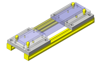
Other Design Consideration
- The spring load can be varied by moving the spring post slot located on the plate. And adjusting bolt is used for adjustments, making it easy to change the spring to vary tension.
Explore Similar Application Examples
Page
-
/
-

-
-
-

-

-
Relevant category
-

-

-

-

-

-

-

Relevant category
-
-

-

-
Relevant category
-

-

-

-

-

-
-

-

-

-

-

-

-

-

-
-

-

-

-

-
-

-


Payment Methods
- Credit Card
-
- Bank
-
- Prompt Pay
-


Social Media
MISUMI Contact
Copyright © MISUMI Corporation All Rights Reserved.